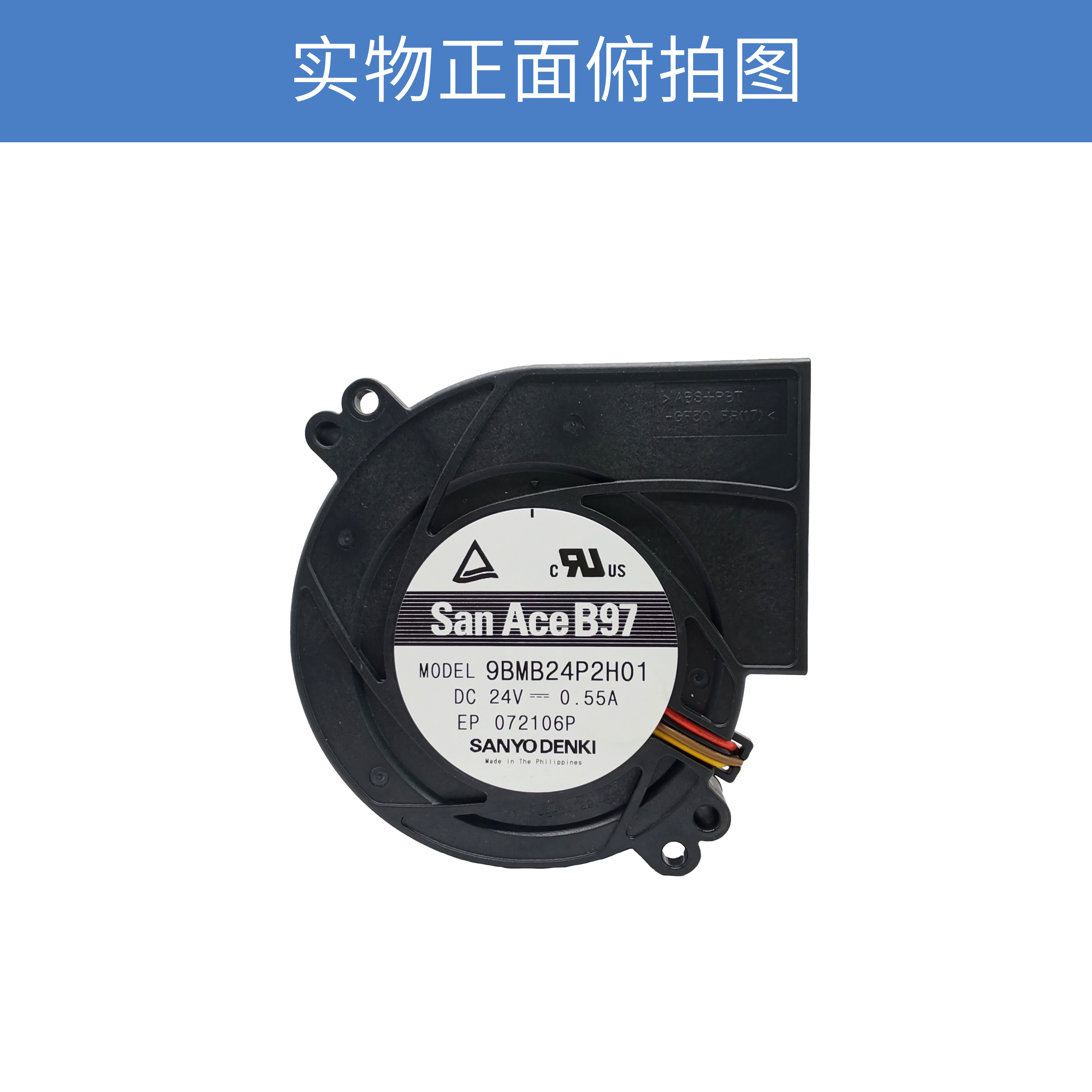
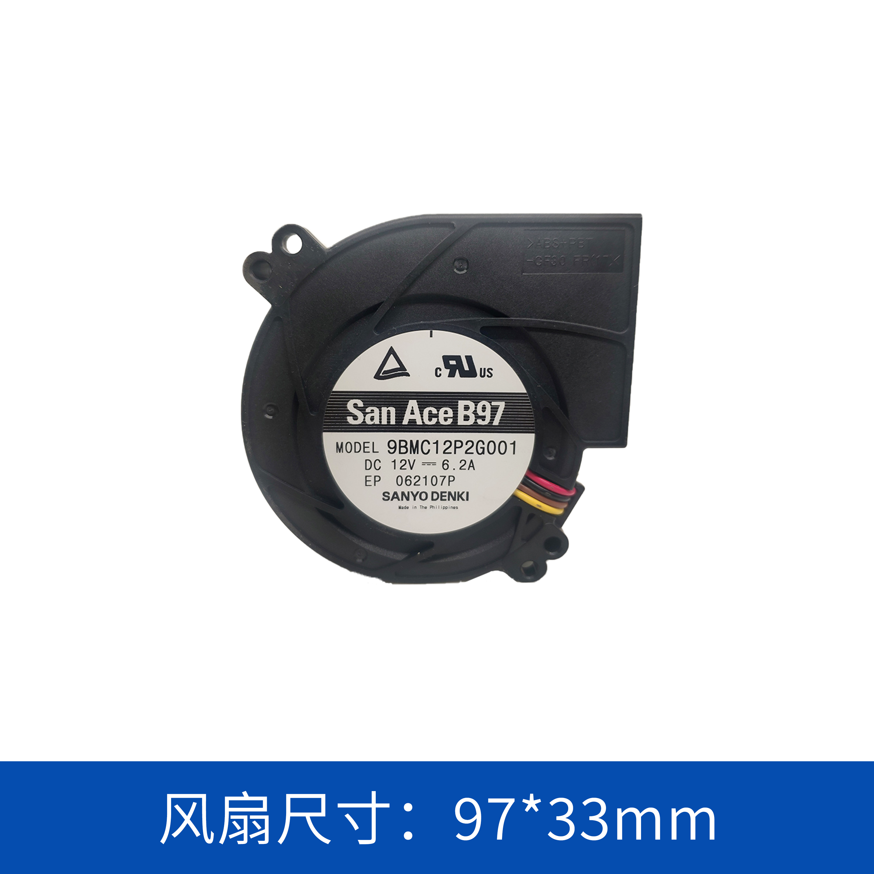
SANYO DENKI San Ace 9BMB24P2H01: 24V 97×33mm DC Blower for High-Resistance Cooling Systems
When cooling components inside a compact electronic system, selecting a fan based only on airflow can lead to an unsuitable thermal solution. In many applications, the cooling airflow must pass through narrow passages, filters, heat sinks, ducts, or densely arranged components. Under these conditions, static pressure becomes an important factor in determining the actual cooling performance.
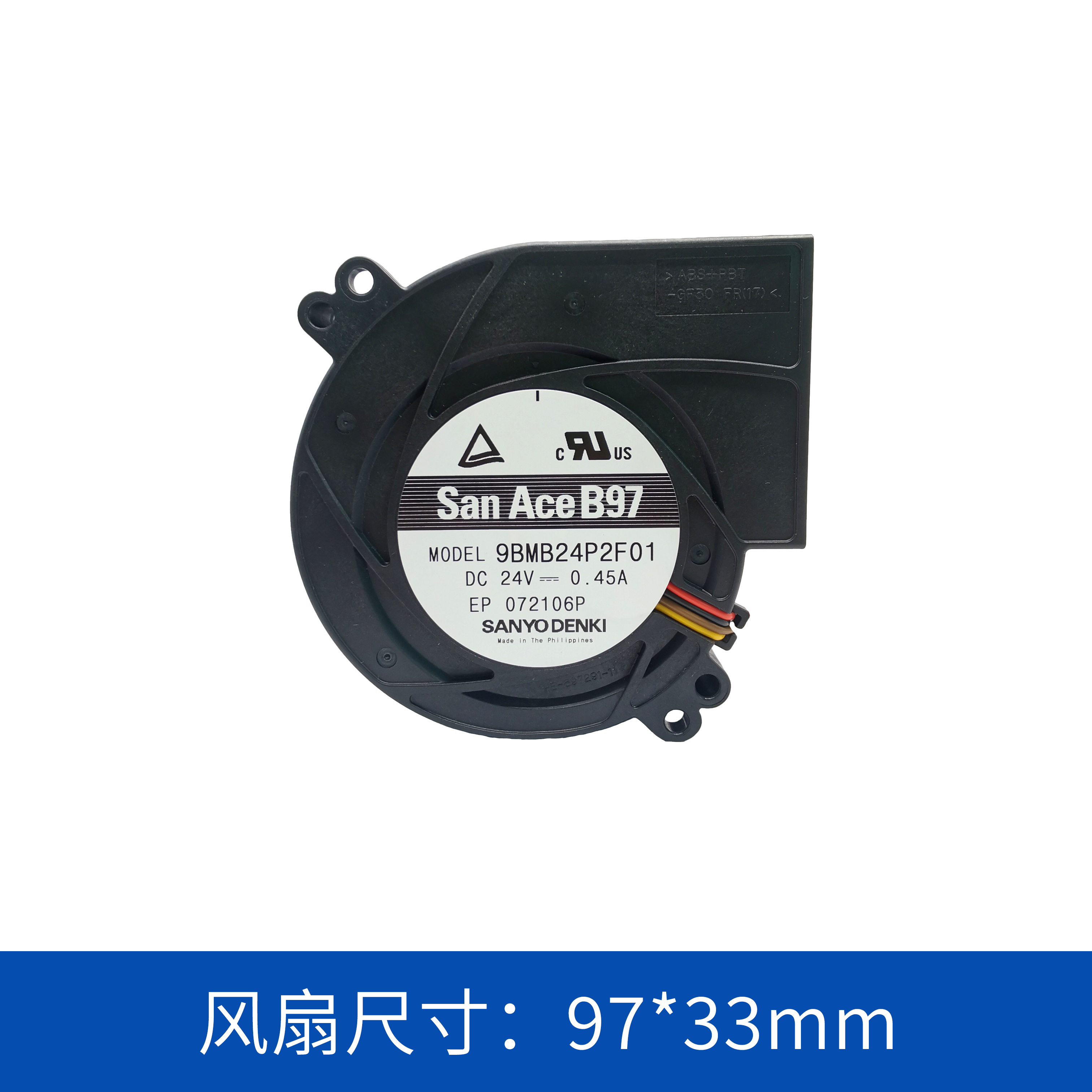
The SANYO DENKI San Ace 9BMB24P2H01 is a 24V DC blower designed for applications where controlled airflow and static pressure are required within a compact installation space.
With a 97×33mm form factor, a maximum airflow of 1.11m³/min (39.2CFM) and maximum static pressure of 490Pa, this blower provides a practical balance between airflow capacity, pressure performance and installation size.
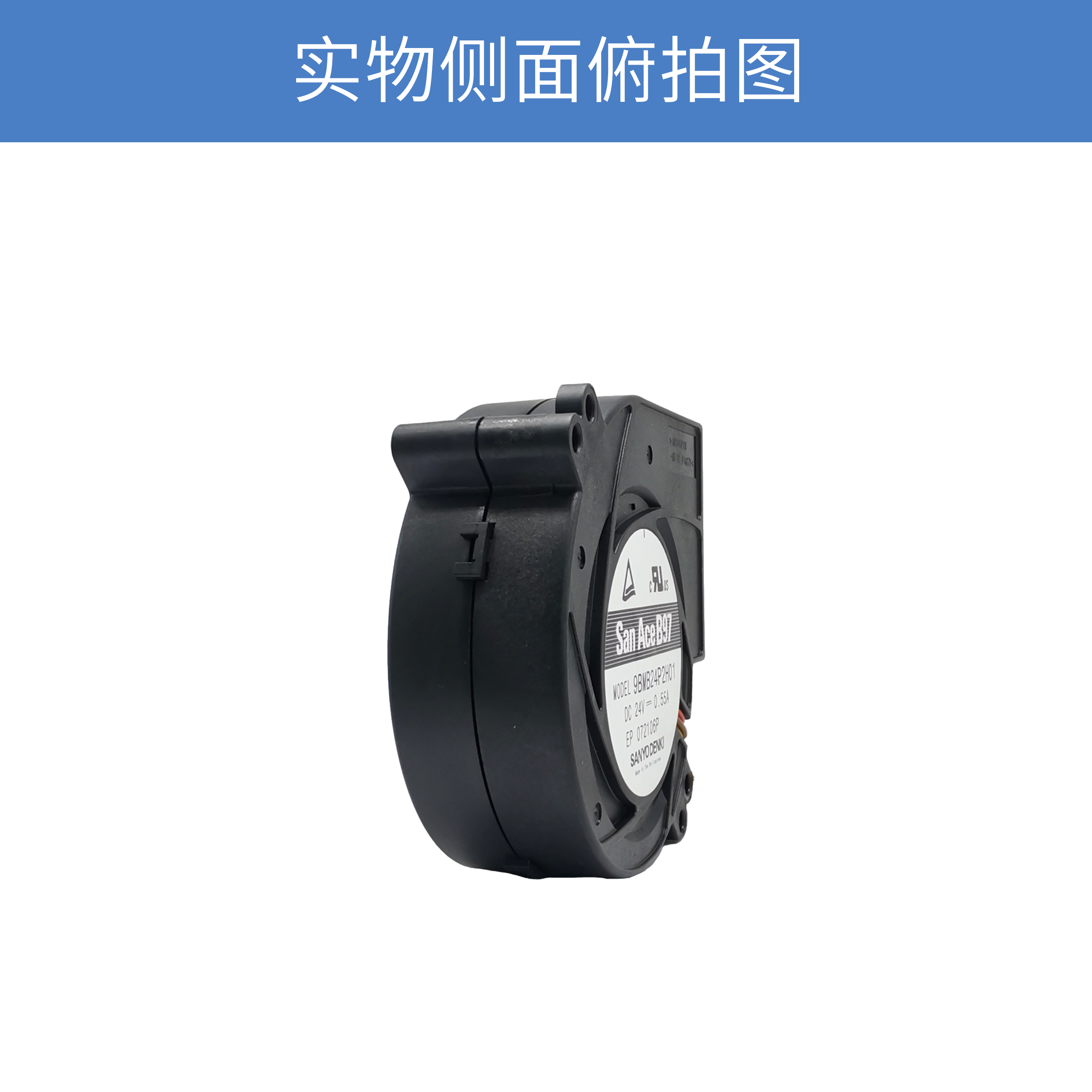
1. Compact 97×33mm Blower Design
The San Ace 9BMB24P2H01 has a compact:
-
97mm × 97mm footprint
-
33mm thickness
-
24V DC rated voltage
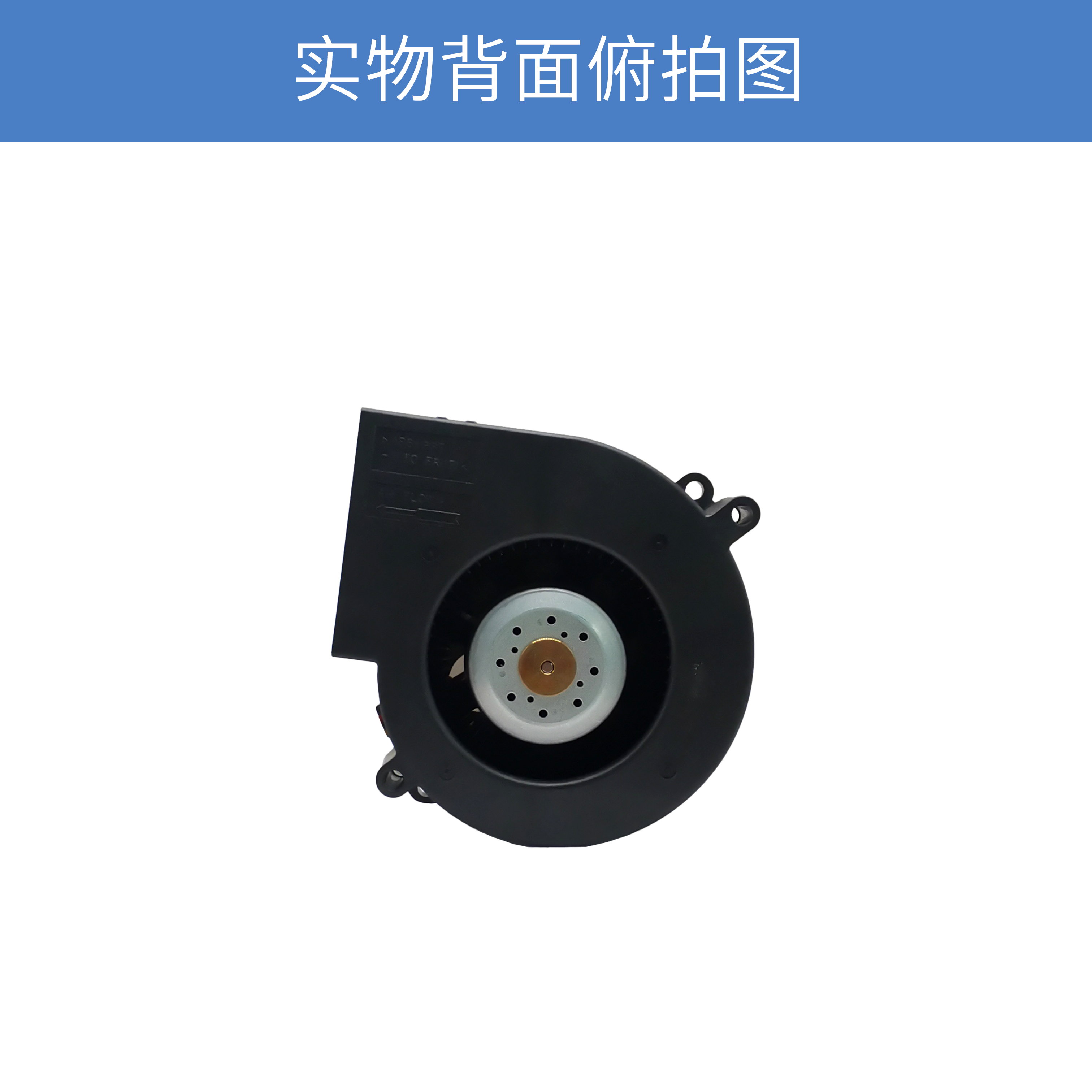
Compared with conventional axial fans, the blower structure is particularly useful when the cooling system requires a change in airflow direction or when the available installation space does not allow a straightforward axial airflow path.
A blower can discharge air approximately 90 degrees from the intake direction, allowing equipment designers to organize the internal airflow path more efficiently without necessarily adding an external air duct.
This can be valuable in compact electronic equipment where PCB layout, heat sinks and enclosure structures leave limited space for conventional fan arrangements.
2. 490Pa Static Pressure for Systems with Airflow Resistance
One of the important specifications of the 9BMB24P2H01 is its maximum static pressure of:
490Pa / 1.968inchH₂O
This specification should be considered together with airflow rather than independently.
In an actual cooling system, the airflow generated by a fan decreases as system resistance increases. Typical sources of resistance include:
-
Heat sink fins
-
Air filters
-
Protective grilles
-
Narrow ventilation openings
-
Internal air ducts
-
Dense electronic components
-
Cable and structural obstructions
For this type of system, simply selecting a fan with a high free-air airflow rating may not provide the expected cooling result.
A blower with suitable pressure characteristics can maintain more effective airflow through a restrictive cooling path.
3. 1.11m³/min Maximum Airflow
The San Ace 9BMB24P2H01 provides a maximum airflow of:
1.11m³/min / 39.2CFM
This airflow capacity makes the blower suitable for compact electronic equipment where forced-air cooling is required but installation space is restricted.
However, the actual airflow in an installed device will depend on the system's pressure loss.
Therefore, engineers should evaluate the blower according to the system operating point, rather than selecting a model solely from its maximum airflow specification.
The relationship between airflow and static pressure is especially important when the cooling system contains multiple resistance components.
4. 4,850min⁻¹ Rated Speed
The rated speed of the 9BMB24P2H01 is:
4,850min⁻¹
At this operating point, the blower provides a maximum airflow of 1.11m³/min and maximum static pressure of 490Pa according to the supplied specifications.
The relatively high rotational speed helps the compact blower generate the pressure required for applications where airflow needs to move through restricted internal paths.
For equipment designers, this makes the 9BMB24P2H01 particularly interesting when the enclosure size is limited but the cooling system still requires meaningful static pressure.
5. PWM Control for Dynamic Thermal Management
The 9BMB24P2H01 supports PWM control.
PWM speed control allows the cooling system to adjust blower operation according to the actual thermal condition of the equipment.
For example, the system can operate the blower at a lower speed when the equipment load is light and increase the cooling capacity when internal temperature or processing load increases.
This approach can provide several potential benefits:
-
Reduced unnecessary fan operation
-
Better acoustic management
-
More efficient thermal control
-
Dynamic adjustment according to equipment load
-
Improved control over system cooling performance
For equipment that operates under variable loads, PWM control can therefore be an important part of the overall thermal-management strategy.
6. Pulse Sensor for Fan Monitoring
The 9BMB24P2H01 is equipped with a pulse sensor.
A pulse output can be used by the host system to monitor blower rotational operation.
In applications where continuous operation and thermal reliability are important, fan monitoring can provide an additional layer of system protection.
For example, the equipment controller can monitor the pulse signal and identify abnormal changes in fan operation. Combined with temperature monitoring, this can help the system detect potential cooling problems before they result in excessive component temperatures.
This feature can be particularly useful for industrial electronic equipment and other systems that are expected to operate continuously.
7. 24V DC Power Supply
The 9BMB24P2H01 is designed for a 24V DC power supply.
Its rated electrical specifications include:
|
Parameter
|
Specification
|
|
Model
|
9BMB24P2H01
|
|
Product type
|
DC Blower
|
|
Brand
|
SANYO DENKI / San Ace
|
|
Dimensions
|
97 × 97 × 33mm
|
|
Rated voltage
|
24V DC
|
|
Rated current
|
0.55A
|
|
Rated power
|
13.2W
|
|
Rated speed
|
4,850min⁻¹
|
|
Maximum airflow
|
1.11m³/min
|
|
Maximum airflow
|
39.2CFM
|
|
Maximum static pressure
|
490Pa
|
|
Maximum static pressure
|
1.968inchH₂O
|
|
Noise
|
57dBA
|
|
Sensor
|
Pulse sensor
|
|
PWM control
|
Yes
|
|
Expected life
|
40,000h at 60°C / 70,000h at 40°C
|
The 24V configuration makes this blower suitable for equipment architectures that already use a 24V DC auxiliary power system.
8. 57dBA Noise Level
The specified noise level of the 9BMB24P2H01 is 57dBA.
Noise should be evaluated together with airflow, static pressure and the actual equipment structure.
In a complete system, enclosure geometry, air outlets, filters, ducts and mounting structures can all affect the final acoustic performance.
Therefore, for applications with strict noise requirements, it is recommended to evaluate the complete cooling assembly rather than judging acoustic performance from the blower specification alone.
9. Expected Service Life
The specified expected life of the San Ace 9BMB24P2H01 is:
40,000 hours at 60°C
or
70,000 hours at 40°C
Operating temperature is an important factor when evaluating fan life.
For equipment intended for continuous operation, thermal conditions around the blower should therefore be considered during mechanical and electrical design.
Proper airflow routing can also help prevent the blower from continuously operating in an unnecessarily high-temperature environment.
10. Where Can the 9BMB24P2H01 Be Used?
The combination of a compact 97×33mm structure, 24V DC input, PWM control, pulse sensing and 490Pa maximum static pressure makes the blower suitable for various electronic cooling applications.
Potential application areas include:
Servers and IT Equipment
High-density server systems often contain heat-generating processors, power modules and memory components within limited internal space.
Airflow paths may include heat sinks and narrow channels, creating significant system impedance. A blower can therefore be considered when pressure performance is more important than simply maximizing free-air airflow.
Communication Equipment
Communication equipment may require continuous forced-air cooling while maintaining a compact enclosure.
The 9BMB24P2H01's 24V configuration and pulse monitoring function can be useful in equipment where fan operation needs to be controlled and monitored.
Industrial Control Equipment
Industrial controllers, automation equipment and control cabinets can contain multiple heat-generating electronic modules.
When the cooling path includes protective structures or compact internal airflow channels, the blower configuration can offer an alternative to conventional axial fans.
Power Electronics
Power supplies, converters and other power-electronic equipment can generate concentrated heat around specific components.
A properly designed blower airflow path can direct cooling air toward these thermal hotspots instead of relying on general enclosure ventilation.
11. Why Choose a Blower Instead of a Conventional Axial Fan?
The key difference is the airflow direction and pressure characteristics.
A conventional axial fan generally moves air along the axis of the fan. This is useful when the equipment has a relatively direct intake-to-exhaust airflow path.
A blower, on the other hand, can redirect the airflow through its outlet.
This provides greater flexibility when designing compact equipment.
For example:
Axial fan
Air intake → Fan → Straight airflow → Heat source → Exhaust
Blower
Air intake
↓
Blower
→ 90° airflow direction → Heat source → Exhaust
This structure can make it easier to integrate forced cooling into equipment where the available installation space is constrained.
12. What Should Engineers Consider When Selecting the 9BMB24P2H01?
The most important consideration is not simply whether the blower has sufficient maximum airflow.
Engineers should evaluate:
① Required airflow
Determine the approximate airflow required to remove the heat generated by the target components.
② System impedance
Identify the pressure loss caused by heat sinks, filters, grilles, ducts and other internal structures.
③ Operating point
Compare the system resistance curve with the blower's P-Q performance curve to determine the actual operating airflow.
④ Installation dimensions
Confirm that the 97×97×33mm dimensions fit the available mounting area.
⑤ Power supply
Verify that the equipment can provide the required 24V DC supply.
⑥ Control method
If the equipment requires variable-speed cooling, the PWM control function should be integrated into the system design.
⑦ Monitoring
The pulse sensor can be incorporated into the equipment controller for rotational-speed monitoring.
13. San Ace 9BMB24P2H01 at a Glance
The SANYO DENKI San Ace 9BMB24P2H01 is a compact 24V DC blower designed for applications where airflow must overcome system resistance.
Its key specifications include 97×97×33mm dimensions, 4,850min⁻¹ rated speed, 1.11m³/min maximum airflow, 490Pa maximum static pressure and 57dBA noise. The blower also provides PWM control and pulse-sensor feedback, allowing it to be integrated into dynamically controlled cooling systems.
For compact servers, communication equipment, industrial controllers, power electronics and other high-density electronic systems, the selection of a blower should be based on the complete system operating point rather than maximum airflow alone.
When the equipment contains narrow airflow passages or significant internal resistance, static pressure, airflow and system impedance should be evaluated together to achieve a reliable cooling design.
 ∷
∷




 Click to inquire