109BM24MC2-1 San Ace Blower: Compact 24V Cooling with 3.6W Rated Power
As industrial electronics become more compact, cooling design is increasingly influenced by power consumption, available installation space and the required airflow path. Not every application requires a high-speed blower with maximum airflow. In many systems, a moderate and stable airflow level can be more appropriate, particularly when the equipment operates continuously and auxiliary power consumption needs to be controlled.
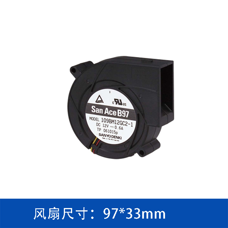
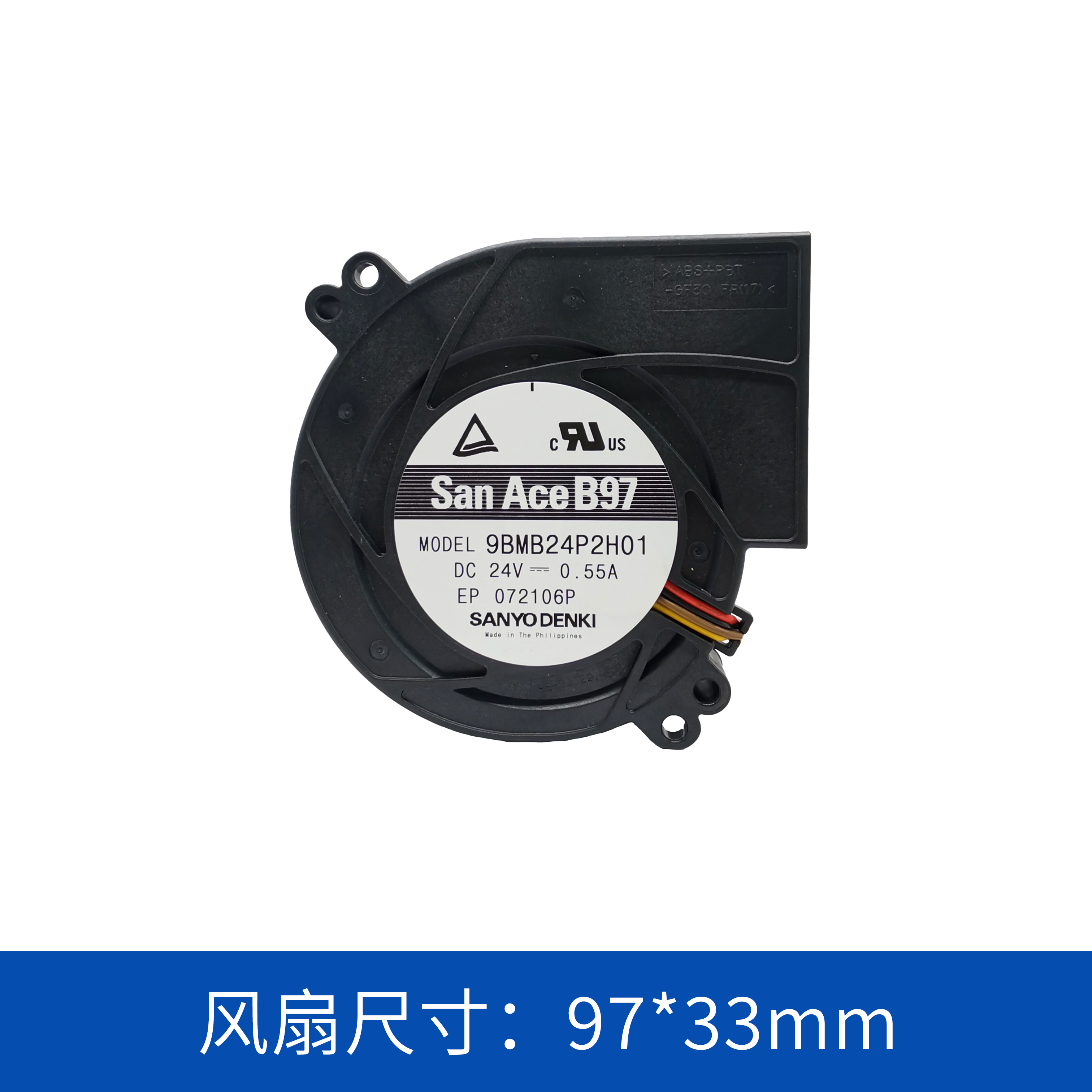
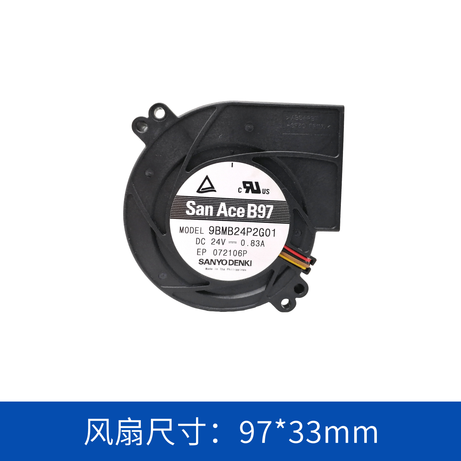
The 109BM24MC2-1 San Ace blower is positioned in this type of application. Manufactured under the San Ace brand of SANYO DENKI, the model operates from a 24V DC supply, uses a 97 × 33 mm form factor, and has a rated power consumption of only 3.6 W.
With a maximum airflow of 20.5 CFM and maximum static pressure of 119 Pa, it provides a compact blower option for electronic and industrial equipment requiring controlled forced-air cooling.
1. A Blower Designed for Moderate Cooling Requirements
Cooling requirements vary significantly between different types of equipment.
High-power computing systems, power converters and large industrial systems may require substantial airflow and high static pressure. Other equipment, however, may have a lower thermal load or a more open airflow structure.
For these applications, choosing a significantly oversized cooling fan can create unnecessary:
-
Power consumption
-
Acoustic output
-
Airflow turbulence
-
Mechanical integration requirements
-
System cost
The 109BM24MC2-1 has a rated speed of 2,700 min-1, maximum airflow of 20.5 CFM and maximum static pressure of 119 Pa.
This places the model toward the moderate-performance side of the 97 × 33 mm blower family, making it useful for applications where balanced cooling performance is more important than maximum airflow.
2. Key Specifications of 109BM24MC2-1
|
Parameter
|
Specification
|
|
Model
|
109BM24MC2-1
|
|
Brand
|
San Ace / SANYO DENKI
|
|
Product Type
|
DC Blower
|
|
Rated Voltage
|
24 V DC
|
|
Rated Current
|
0.15 A
|
|
Rated Power
|
3.6 W
|
|
Rated Speed
|
2,700 min-1
|
|
Dimensions
|
97 × 33 mm
|
|
Maximum Airflow
|
0.58 m³/min / 20.5 CFM
|
|
Maximum Static Pressure
|
119 Pa / 0.478 inchH₂O
|
|
Noise
|
43.5 dBA
|
|
Expected Life
|
40,000 h at 60°C / 70,000 h at 40°C
|
|
Sensor
|
Pulse sensor
|
|
PWM Control
|
No
|
|
Ribbed
|
No
|
The specifications show a clear focus on moderate airflow and low electrical consumption.
At 3.6 W rated power, the blower can be considered where fan power needs to remain a relatively small portion of the overall equipment power budget.
3. Why 3.6W Power Consumption Matters in Continuous-Running Equipment
Cooling fans often operate for long periods, especially in:
-
Communication equipment
-
Industrial controllers
-
Network equipment
-
Electronic control systems
-
Instrumentation
-
Power supply systems
When a cooling fan operates continuously, even a small difference in rated power can accumulate over the operating life of the equipment.
The 109BM24MC2-1 is rated at:
24 V × 0.15 A = 3.6 W
For equipment designers, this provides a useful reference when calculating auxiliary power consumption.
If multiple fans are used, the total fan power should also be considered.
For example, a system using four units would have a nominal fan power consumption of approximately 14.4 W at the stated rated conditions.
The actual operating consumption will depend on the application and operating conditions, but the rated value provides a starting point for system-level power calculations.
4. 20.5 CFM Airflow for Compact Equipment
The maximum airflow of the 109BM24MC2-1 is 20.5 CFM, equivalent to approximately 0.58 m³/min.
This level of airflow can be relevant to equipment where the primary objective is to remove heat from a relatively small enclosure or direct air toward selected components.
However, engineers should avoid treating maximum airflow as the actual airflow inside the finished product.
Once a blower is installed, airflow is affected by:
-
Air inlet resistance
-
Outlet resistance
-
Duct dimensions
-
Heat sinks
-
Filters
-
Protective grilles
-
Internal partitions
-
Cable routing
Therefore, the actual operating point should be evaluated using the system resistance and the blower's performance curve.
5. 119Pa Static Pressure: An Important Selection Parameter
The maximum static pressure of the 109BM24MC2-1 is 119 Pa.
For an open airflow path, maximum airflow may be the more obvious specification. However, when air must pass through a restricted path, pressure capability becomes increasingly important.
Consider an enclosure where the cooling air must travel through:
Air inlet → electronic module → heat sink → internal duct → exhaust
Every section introduces resistance.
If the system resistance becomes too high, the actual airflow can be significantly lower than the catalogue maximum airflow.
This is why engineers should evaluate both:
Airflow requirement + System resistance
rather than selecting a blower according to CFM alone.
For applications with relatively modest airflow resistance, the 119 Pa pressure capability may provide an appropriate balance between airflow and power consumption.
6. 43.5 dBA Noise Level
The specified noise level of the 109BM24MC2-1 is 43.5 dBA.
Compared with higher-speed models in the same product family, the lower rated speed of 2,700 min-1 corresponds to a more moderate operating profile.
Nevertheless, the final noise level of a complete machine cannot be determined solely from the fan specification.
Equipment designers should also consider:
-
Fan mounting method
-
Enclosure resonance
-
Airflow turbulence
-
Duct design
-
Inlet and outlet geometry
-
Nearby heat sinks
-
Panel vibration
A well-designed airflow path can help avoid unnecessary turbulence and associated acoustic issues.
7. 97 × 33mm Size for Space-Constrained Designs
Mechanical packaging is often a significant challenge in modern electronic equipment.
A cooling solution may have to fit around:
-
PCBs
-
Power supplies
-
Cable assemblies
-
Heat sinks
-
Connectors
-
Structural brackets
The 97 × 33 mm dimensions of the 109BM24MC2-1 provide a compact blower format that can be considered where installation space is limited.
However, the dimensions of the blower itself should not be the only mechanical consideration.
Engineers should reserve sufficient space around the inlet and outlet to ensure that the airflow path is not unnecessarily restricted.
A compact fan installed into an unsuitable airflow opening may deliver considerably less practical cooling performance than expected.
8. Pulse Sensor for Basic Operating Monitoring
The 109BM24MC2-1 includes a Pulse sensor.
This allows the equipment's control system to monitor fan operation through the available pulse signal.
In industrial equipment, such feedback can support functions such as:
-
Fan rotation monitoring
-
Fan failure detection
-
Maintenance alerts
-
Cooling-system diagnostics
-
Equipment protection logic
For continuously operating equipment, this can be particularly useful because a fan failure may otherwise remain unnoticed until the internal temperature rises sufficiently to affect other components.
The pulse signal can therefore become part of a broader equipment reliability strategy.
9. Expected Life at Different Operating Temperatures
The specified expected life is:
40,000 hours at 60°C
or
70,000 hours at 40°C.
This difference illustrates why operating temperature should be included when evaluating fan reliability.
The cooling system is intended to protect electronic components from excessive heat, but the fan itself is also operating within the same thermal environment.
When designing the equipment, engineers should consider:
-
Ambient temperature
-
Internal temperature
-
Continuous operating conditions
-
Heat accumulation
-
Airflow restrictions
-
Dust and contamination
-
Maintenance requirements
Improving the equipment's overall thermal design can help reduce thermal stress on both the fan and the electronic components.
10. Potential Applications
The characteristics of the 109BM24MC2-1 make it suitable for consideration in applications where moderate forced-air cooling is required.
Industrial Controllers
Industrial controllers can contain processors, communication modules and power electronics inside relatively compact enclosures. A blower can help establish a defined airflow route through the enclosure.
Communication Equipment
Communication devices frequently operate continuously, making power consumption and long-term reliability important design considerations.
Electronic Control Systems
Control electronics may have several localized heat sources. A blower can be used to direct cooling air toward these areas instead of relying entirely on natural convection.
Instrumentation
Measurement and control equipment may require stable operating temperatures to maintain consistent performance. A moderate-power blower can provide forced cooling without introducing excessive airflow.
Power Supply Equipment
Power supplies generate heat through switching devices, transformers and other components. Depending on the thermal load and airflow resistance, a compact blower can be evaluated as part of the cooling architecture.
11. How to Determine Whether 109BM24MC2-1 Is Suitable
The correct selection process should start from the equipment rather than the fan.
Step 1: Calculate the heat load
Identify the major heat-generating components and estimate the total heat that must be removed.
Step 2: Determine the required airflow
Establish the airflow required to maintain the target component or enclosure temperature.
Step 3: Analyze airflow resistance
Estimate pressure losses caused by:
-
Filters
-
Grilles
-
Heat sinks
-
Ducts
-
Vents
-
Internal structures
Step 4: Identify the operating point
Use the blower performance curve together with the system resistance curve.
Step 5: Validate with a prototype
Measure:
-
Component temperature
-
Air temperature
-
Fan operating condition
-
Noise
-
Power consumption
under realistic operating loads.
This final validation is particularly important because catalogue maximum values do not represent the complete system operating condition.
12. Moderate Cooling Can Sometimes Be More Appropriate Than Maximum Cooling
There is a tendency in thermal design to select the fan with the highest airflow available.
However, higher airflow does not automatically mean a better cooling system.
If the equipment only requires moderate airflow, an oversized blower can introduce unnecessary power consumption and acoustic output.
The 109BM24MC2-1 offers a different design approach:
24V DC + 3.6W rated power + 20.5 CFM maximum airflow + 119 Pa maximum static pressure
This combination can be considered when the cooling requirement is moderate and the system designer wants to balance thermal performance with auxiliary power consumption.
The appropriate model ultimately depends on the equipment's actual thermal load and airflow resistance.
13. Conclusion
The 109BM24MC2-1 San Ace blower from SANYO DENKI is a compact 24V DC blower measuring 97 × 33 mm and rated at 3.6 W and 2,700 min-1.
Its maximum airflow is 20.5 CFM, while maximum static pressure reaches 119 Pa. With a specified noise level of 43.5 dBA, Pulse sensor feedback and an expected life of 40,000 hours at 60°C or 70,000 hours at 40°C, the model provides a practical option for moderate forced-air cooling requirements.
Rather than focusing only on maximum airflow, engineers evaluating this model should consider the complete thermal system: heat generation, airflow resistance, installation space, power consumption, noise requirements and operating temperature.
For compact 24V industrial and electronic equipment, the 109BM24MC2-1 can therefore be evaluated as a low-power San Ace blower option where controlled airflow is required without unnecessarily high fan power consumption.
Product Summary
-
Model: 109BM24MC2-1
-
Brand: San Ace / SANYO DENKI
-
Type: DC Blower
-
Rated Voltage: 24 V DC
-
Rated Current: 0.15 A
-
Rated Power: 3.6 W
-
Rated Speed: 2,700 min-1
-
Size: 97 × 33 mm
-
Maximum Airflow: 20.5 CFM
-
Maximum Static Pressure: 119 Pa
-
Noise: 43.5 dBA
-
Expected Life: 40,000 h at 60°C / 70,000 h at 40°C
-
Sensor: Pulse sensor
-
PWM Control: No
-
Ribbed: No
 ∷
∷




 Click to inquire