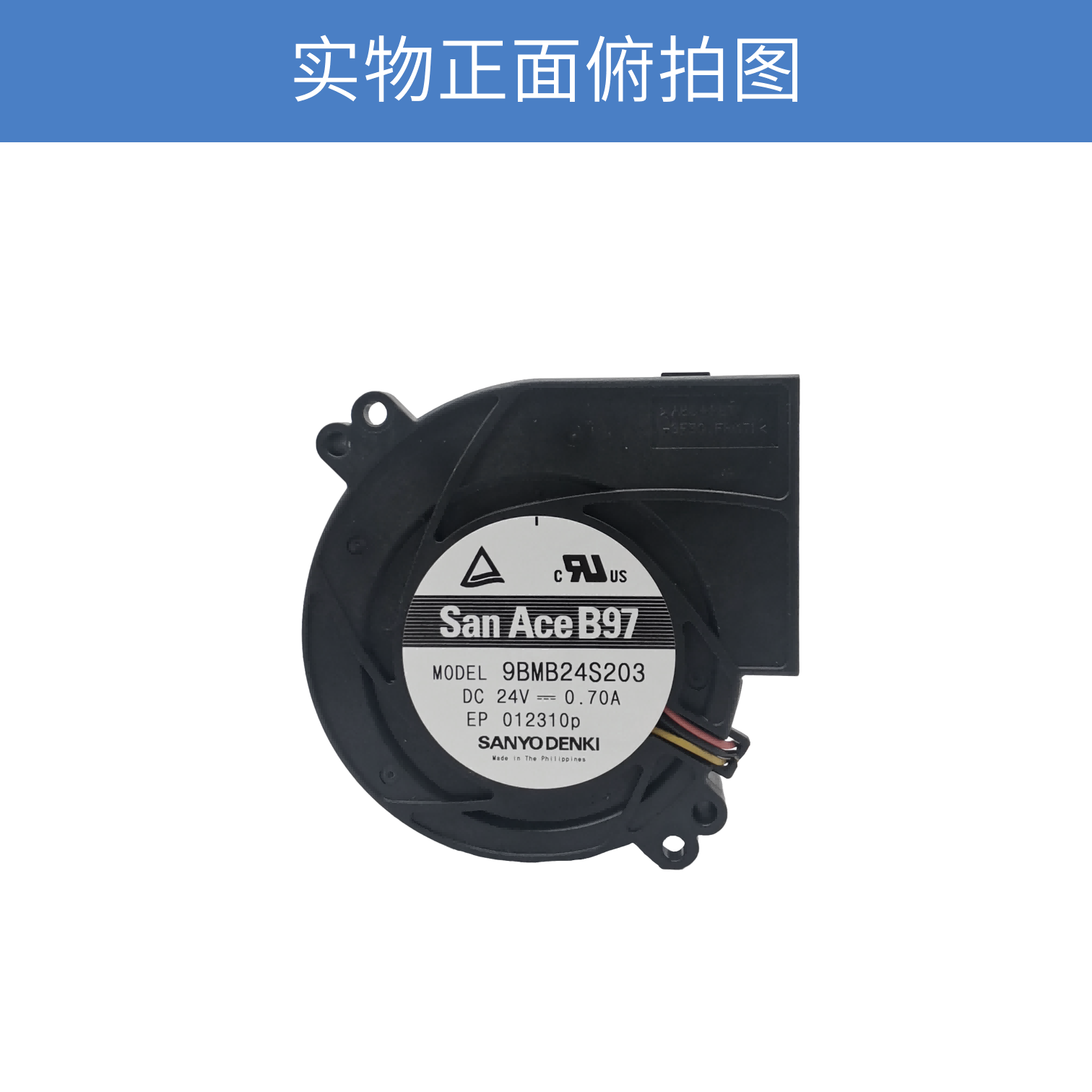
SANYO DENKI San Ace 9BMB24S201 24V 9733 DC Blower Fan
When cooling components inside a compact electronic enclosure, the available installation space and airflow path can be just as important as the required airflow itself. A conventional axial fan may provide sufficient airflow in an open environment, but the situation changes when the air needs to be redirected through a restricted internal path.
The SANYO DENKI San Ace 9BMB24S201 is a 24V DC blower designed for this type of cooling configuration.
With a 97 × 97 × 33 mm size, the blower provides a maximum airflow of 43.1 CFM and maximum static pressure of 610 Pa. It operates at a rated speed of 5,250 min-1 and has a rated power consumption of 16.8 W.
The model also features a pulse sensor, providing rotational feedback for equipment-level monitoring.
San Ace 9BMB24S201 Specifications
|
Parameter
|
Specification
|
|
Model
|
9BMB24S201
|
|
Brand
|
SANYO DENKI San Ace
|
|
Product Type
|
DC Blower
|
|
Size
|
97 × 97 mm
|
|
Thickness
|
33 mm
|
|
Rated Voltage
|
24 V DC
|
|
Rated Current
|
0.7 A
|
|
Rated Power
|
16.8 W
|
|
Rated Speed
|
5,250 min-1
|
|
Maximum Airflow
|
1.22 m³/min / 43.1 CFM
|
|
Maximum Static Pressure
|
610 Pa / 2.45 inchH₂O
|
|
Noise Level
|
59 dBA
|
|
Sensor
|
Pulse Sensor
|
|
PWM Control
|
No
|
|
Expected Life
|
40,000 h at 60°C / 70,000 h at 40°C
|
The combination of a compact footprint, 24V operation and moderate airflow pressure performance makes this model suitable for a range of forced-air cooling applications.
24V DC Blower for Equipment-Level Cooling
The 24V DC configuration is one of the practical characteristics of the 9BMB24S201.
A 24V power architecture is commonly found in industrial electronic equipment and other systems where DC power is already available.
The model has a rated current of 0.7 A and rated power of 16.8 W.
This gives equipment designers a relatively straightforward starting point for evaluating the fan's power requirements during the electrical design stage.
However, the fan should not be considered independently from the equipment power system. The available supply capacity, startup characteristics, control method and operating environment should all be checked during system integration.
97 × 97 × 33 mm Blower Configuration
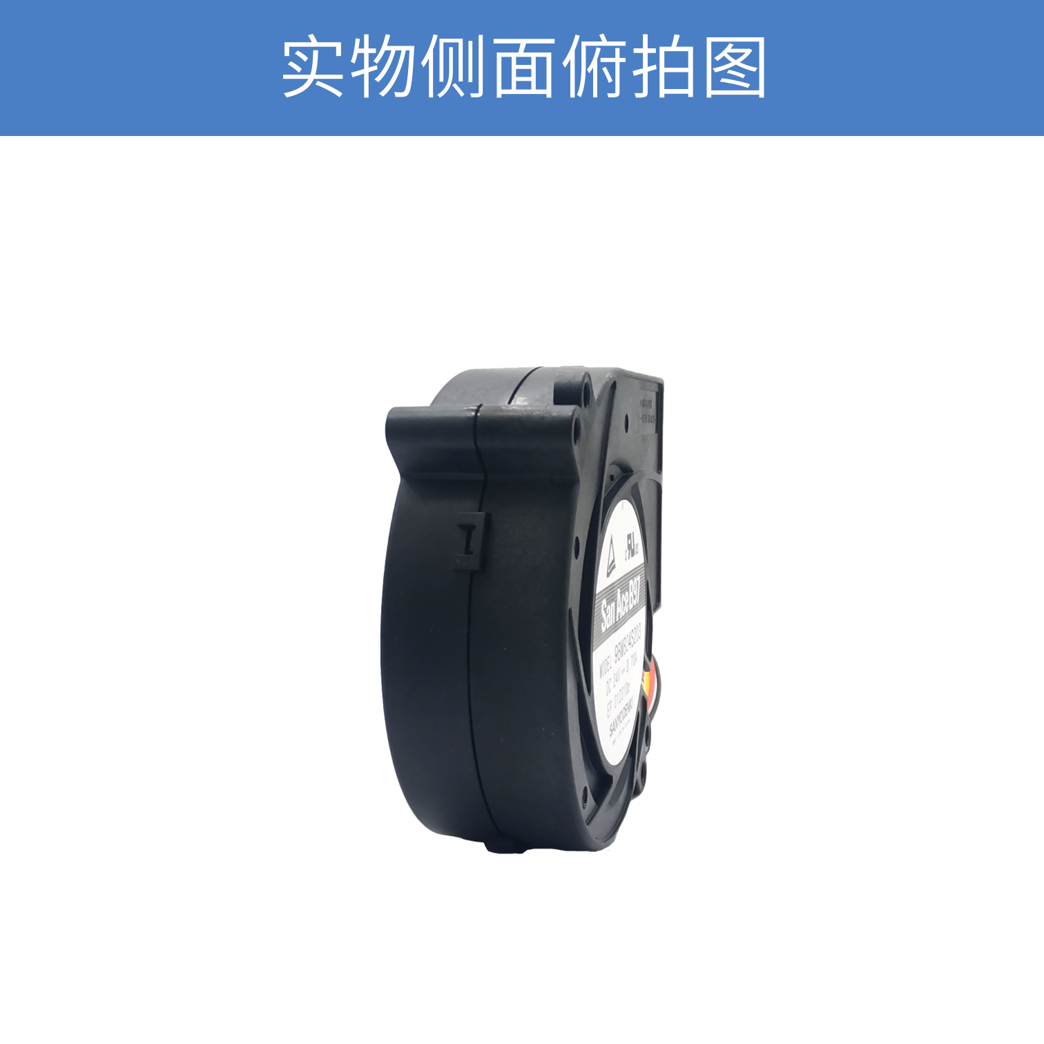
The 97 × 97 × 33 mm dimensions give the 9BMB24S201 a compact installation envelope.
The blower configuration is particularly useful when the required airflow direction does not align with the fan's intake direction.
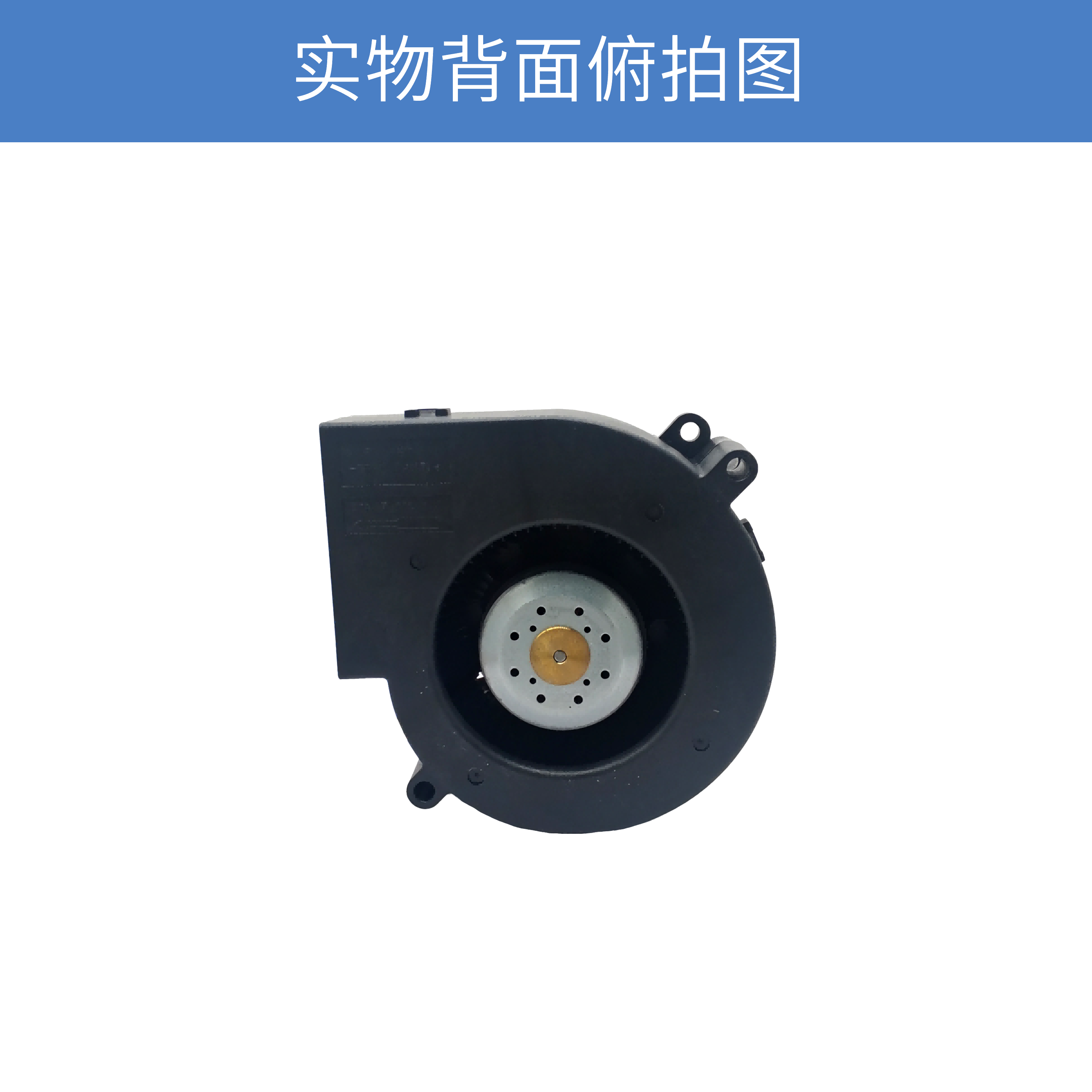
Unlike a conventional axial fan, a blower can discharge air approximately 90 degrees from the intake direction. This allows engineers to design the airflow route around internal components and enclosure structures.
For compact equipment, this can simplify the mechanical arrangement of the cooling system.
Instead of positioning an axial fan directly in line with the target component, the blower can be installed where space is available and the discharge airflow can be directed toward the required cooling path.
43.1 CFM Airflow and 610 Pa Static Pressure
The 9BMB24S201 provides a maximum airflow of 43.1 CFM, equivalent to 1.22 m³/min.
Its maximum static pressure is 610 Pa, or 2.45 inchH₂O.
These specifications are important when evaluating the blower for an enclosed cooling system.
In practical equipment, airflow normally encounters resistance from components such as:
-
Heatsinks
-
Air filters
-
Ventilation openings
-
Narrow airflow channels
-
PCB assemblies
-
Protective grilles
-
Internal ducts
The greater the resistance, the more important static pressure becomes.
Therefore, the 43.1 CFM figure should not be interpreted as the airflow that will necessarily be delivered after installation. The actual airflow depends on the intersection between the fan performance curve and the equipment system resistance.
A Blower Can Help Simplify Internal Airflow Layout
One of the main differences between a blower and an axial cooling fan is the direction in which air is discharged.
For equipment designers, this provides more flexibility when arranging internal airflow.
For example, an enclosure may have limited space above a heat-generating PCB but sufficient space along the side of the assembly.
With an axial fan, the available airflow direction may create mechanical conflicts.
A blower can instead draw air through its intake and redirect the airflow through the outlet, allowing the cooling path to be arranged around the internal structure.
This is particularly useful in compact equipment where PCB placement, heatsink position and enclosure dimensions have already been determined.
5,250 min-1 Rated Speed
The rated speed of the 9BMB24S201 is 5,250 min-1.
At the specified operating condition, the model provides:
-
43.1 CFM maximum airflow
-
610 Pa maximum static pressure
-
59 dBA noise
-
16.8 W rated power
-
0.7 A rated current
The performance profile makes the model an option for applications that require more than simple free-air ventilation but do not necessarily require the higher power levels of the most powerful models in the same size family.
This can be useful when the cooling requirement is moderate and the designer wants to avoid unnecessarily large fan power consumption.
Pulse Sensor for Fan Status Monitoring
The 9BMB24S201 is equipped with a pulse sensor.
A pulse output can provide rotational information to the equipment controller.
This allows the cooling system to do more than simply supply power to the fan. The controller can also monitor whether the blower is rotating normally.
In equipment designed for long-term or continuous operation, this information can be useful for:
-
Fan failure detection
-
Abnormal speed monitoring
-
Preventive maintenance
-
Thermal protection strategies
-
System fault alarms
The pulse sensor can therefore be considered part of the equipment-level cooling monitoring architecture.
Where Can the 9BMB24S201 Be Used?
The performance and mechanical format of the 9BMB24S201 allow it to be considered for various electronic cooling applications.
Industrial Electronic Equipment
Industrial control equipment often has a compact internal structure containing power supplies, control boards and communication modules.
A blower can provide a convenient way to move cooling air through these internal structures.
The 24V DC specification is also suitable for equipment using a 24V control or auxiliary power architecture.
Communication Equipment
Communication and network equipment frequently requires continuous forced-air cooling.
The blower configuration provides additional flexibility when the airflow path needs to be redirected around internal components.
Power Supplies and Power Electronics
Power conversion components can generate concentrated heat, particularly around switching devices, transformers and heatsinks.
The 9BMB24S201 can be considered where the cooling path has moderate airflow resistance and a compact blower configuration is preferred.
Industrial Computing Equipment
Industrial computers and embedded systems often combine relatively high processing loads with limited enclosure space.
The 97 × 97 × 33 mm form factor can provide a useful option when a compact cooling architecture is required.
How to Evaluate the 9BMB24S201 for a New Design
Selecting a blower should begin with the equipment rather than the fan specification sheet.
1. Determine the Heat Load
First estimate the amount of heat that needs to be removed from the enclosure or specific components.
The required cooling capacity should then be translated into an airflow requirement.
2. Analyze Airflow Resistance
Next, evaluate the cooling path.
A system with multiple restrictions may require substantially more static pressure than an open enclosure.
The 610 Pa maximum static pressure of the 9BMB24S201 should therefore be evaluated against the actual system impedance.
3. Check the Installation Envelope
The fan requires a mounting space corresponding to its 97 × 97 × 33 mm dimensions.
The intake and discharge areas should also be designed to avoid unnecessary flow restrictions.
4. Evaluate Acoustic Requirements
The specified noise level is 59 dBA.
Actual equipment noise can differ from the fan's specification because enclosure resonance, airflow turbulence, mounting structure and other components can contribute to overall system noise.
5. Confirm the Electrical Interface
The model operates at 24 V DC, with a rated current of 0.7 A and rated power of 16.8 W.
The power supply and control circuit should be checked for appropriate operating margin.
9BMB24S201 Compared with Higher-Power Blower Models
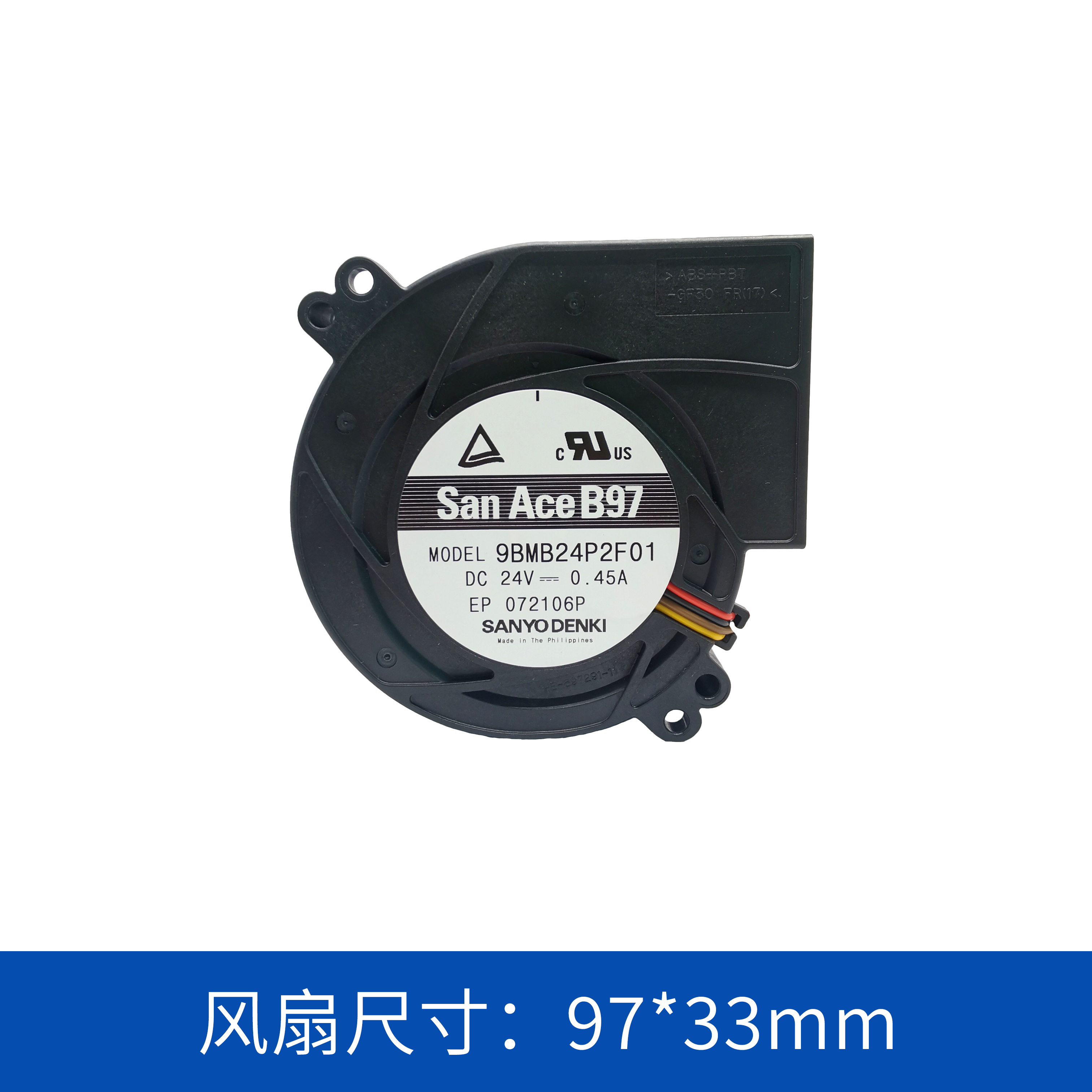
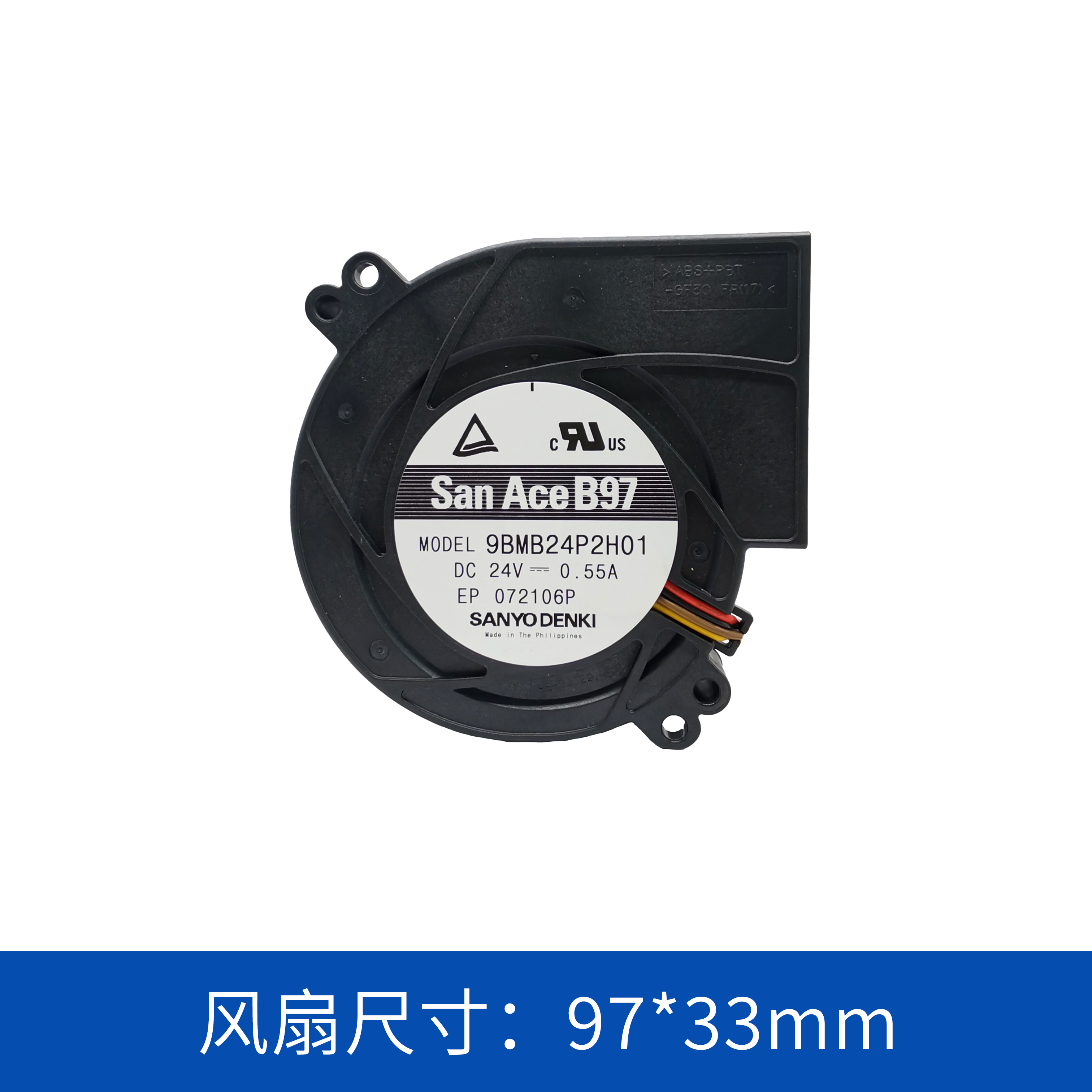
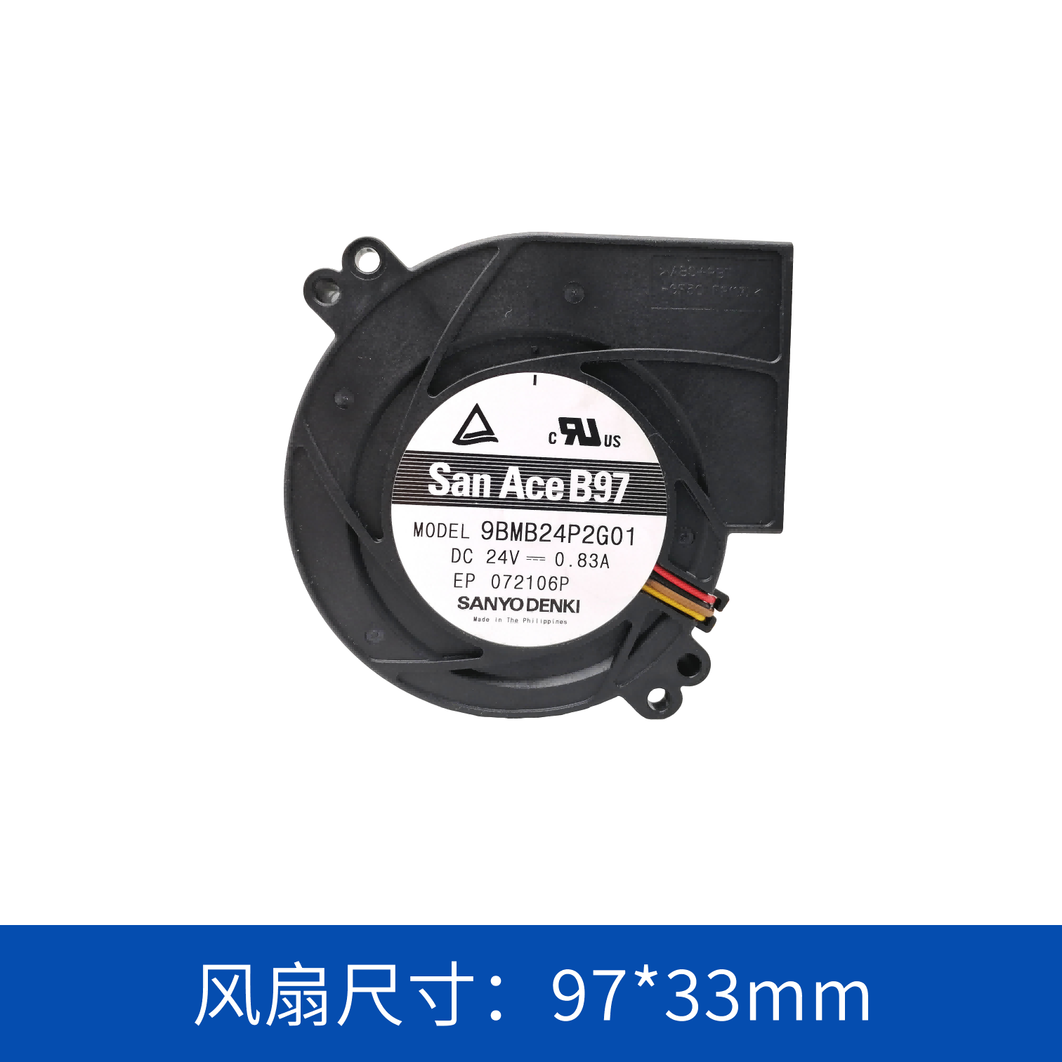
Within the same 97 × 33 mm blower family, different models provide different combinations of airflow, static pressure, speed, power and noise.
This means the highest-performance model is not automatically the best choice.
For equipment with a moderate thermal load, selecting an unnecessarily powerful blower can increase electrical consumption and acoustic output without providing a meaningful thermal benefit.
The 9BMB24S201, with its 43.1 CFM airflow, 610 Pa static pressure and 16.8 W rated power, provides another performance level for engineers to consider when matching fan characteristics to actual system requirements.
The appropriate model should ultimately be determined from the complete fan performance curve, system impedance, thermal load and installation conditions.
San Ace 9BMB24S201 Summary
The SANYO DENKI San Ace 9BMB24S201 is a 24V DC 97 × 97 × 33 mm blower fan designed for compact forced-air cooling systems.
Its principal specifications include:
-
24 V DC rated voltage
-
0.7 A rated current
-
16.8 W rated power
-
5,250 min-1 rated speed
-
43.1 CFM maximum airflow
-
610 Pa maximum static pressure
-
59 dBA noise level
-
Pulse sensor
-
40,000 hours expected life at 60°C
-
70,000 hours expected life at 40°C
For engineers designing industrial electronics, communication equipment, power electronics and compact computing systems, the 9BMB24S201 can be evaluated when the application requires a 24V blower with moderate airflow, useful static-pressure capability and a compact 97 × 33 mm form factor.
Rather than selecting a cooling fan solely by its maximum CFM rating, the most reliable approach is to match the blower's performance to the actual thermal load, system resistance, airflow direction, installation space and electrical architecture of the target equipment.
 ∷
∷




 Click to inquire