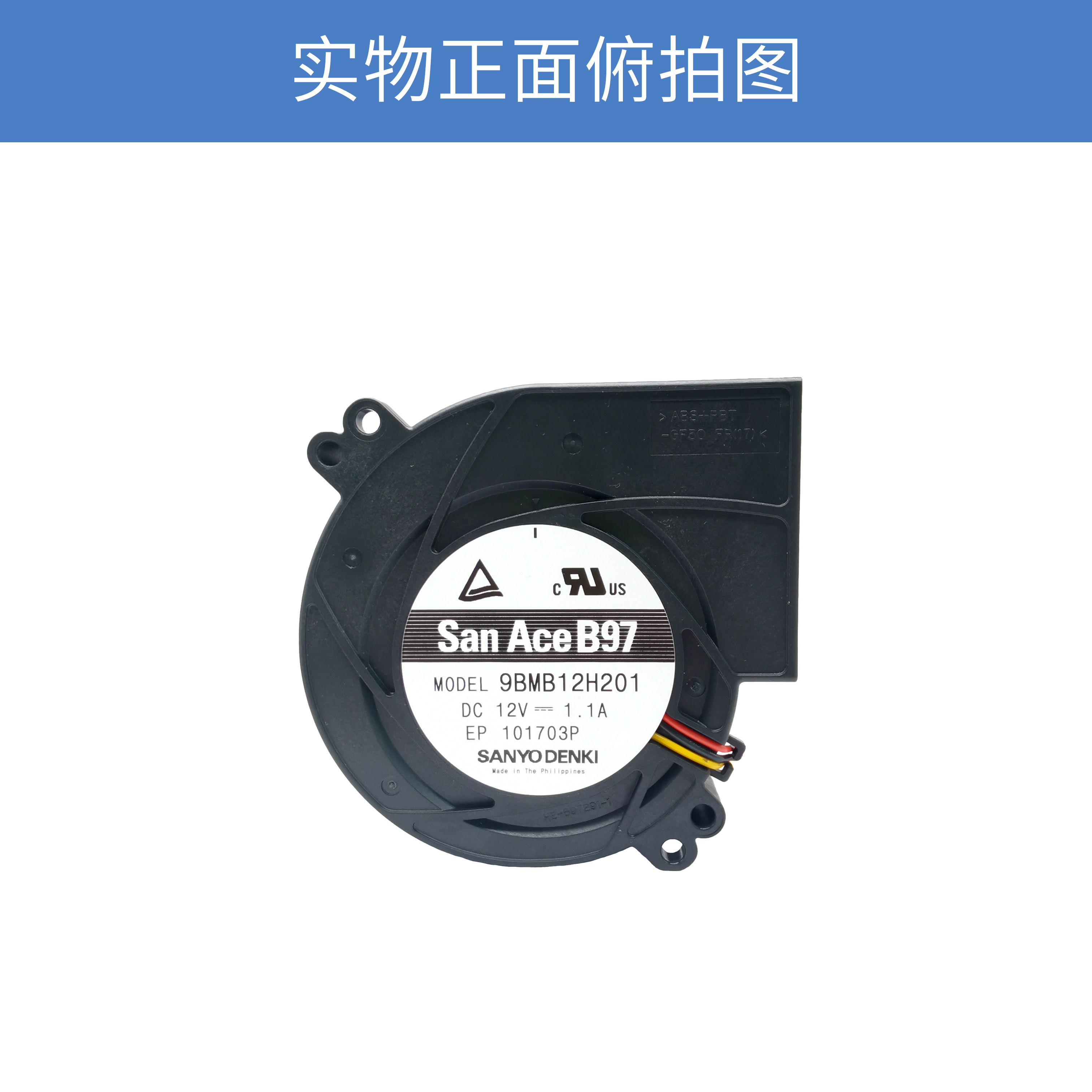
San Ace 9BMB12H201 12V DC Blower for Compact High-Resistance Cooling Systems
When thermal management equipment has limited installation space, simply increasing airflow is not always the most effective solution. Internal components, narrow air passages, filters, heat sinks and system ducts can create considerable airflow resistance. In these applications, the cooling fan needs to maintain sufficient airflow under system resistance rather than only deliver a high free-air airflow value.
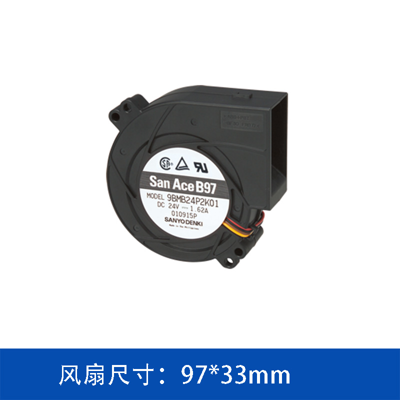
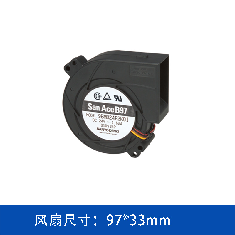
The SANYO DENKI San Ace 9BMB12H201 is a compact 97×33mm DC blower designed for applications where directional airflow and static pressure are important. With a rated voltage of 12 V, a rated speed of 4,850 min⁻¹, maximum airflow of 39.2 CFM and maximum static pressure of 490 Pa, this model provides a practical cooling option for compact electronic equipment.
1. Key Specifications of San Ace 9BMB12H201
The 9BMB12H201 belongs to the San Ace 97×33mm DC blower lineup. Its compact form factor allows it to be integrated into equipment where installation depth and internal airflow routing are restricted.
|
Specification
|
9BMB12H201
|
|
Product Type
|
DC Blower
|
|
Model
|
9BMB12H201
|
|
Size
|
97 × 97 × 33 mm
|
|
Rated Voltage
|
12 V DC
|
|
Rated Current
|
1.1 A
|
|
Rated Power
|
13.2 W
|
|
Rated Speed
|
4,850 min⁻¹
|
|
Maximum Airflow
|
1.11 m³/min
|
|
Maximum Airflow
|
39.2 CFM
|
|
Maximum Static Pressure
|
490 Pa
|
|
Maximum Static Pressure
|
1.968 inchH₂O
|
|
Noise Level
|
57 dBA
|
|
Sensor
|
Pulse Sensor
|
|
Expected Life
|
40,000 h at 60°C / 70,000 h at 40°C
|
|
PWM Control
|
No
|
The combination of 39.2 CFM airflow and 490 Pa maximum static pressure makes this model particularly relevant when a cooling system needs to overcome airflow resistance within a relatively compact enclosure.
2. Why Use a Blower Instead of a Conventional Axial Fan?
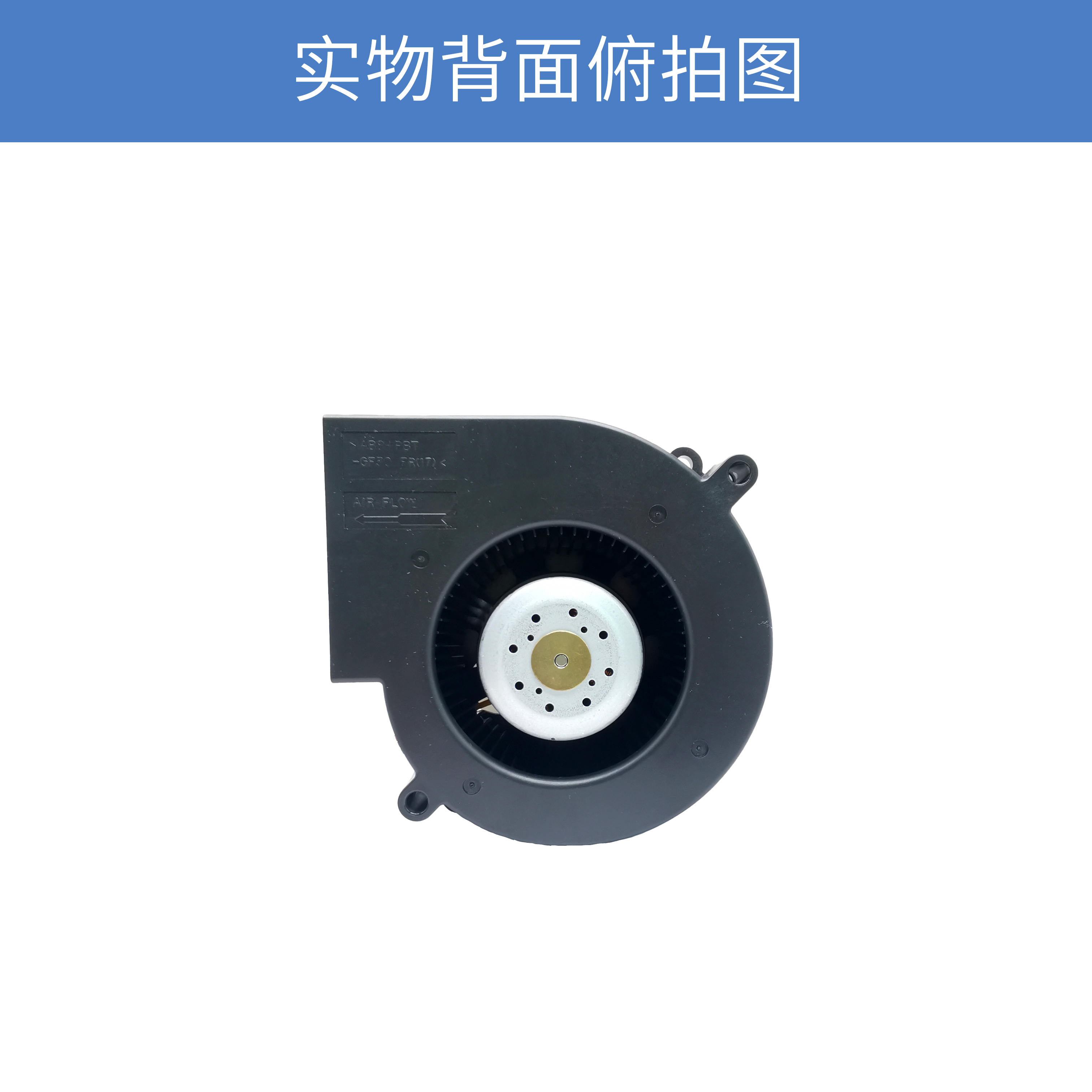
A conventional axial fan generally moves air along the same general axis as its intake direction. A blower, by contrast, is designed to redirect the airflow through its outlet.
This configuration can be useful when the equipment structure does not allow a straight-through airflow path.
For example, the cooling architecture may require air to:
enter from one direction → pass through the blower → turn 90° → move toward the heat-generating components.
A blower can therefore simplify the airflow path without requiring a separate external duct to change the direction of the air.
This is especially useful in compact electronic equipment where PCB arrangement, heat sinks and mechanical structures leave limited room for a conventional axial fan.
3. 490 Pa Static Pressure for Airflow-Resistant Systems
One of the important specifications of the 9BMB12H201 is its maximum static pressure of 490 Pa.
In practical equipment design, the maximum airflow value shown on a fan datasheet represents operation under a particular test condition. Once the fan is installed inside an actual device, airflow resistance changes the operating point.
Resistance may come from:
-
Heat sinks
-
Air filters
-
Narrow ventilation openings
-
Internal ducts
-
Protective grilles
-
Dense electronic assemblies
-
Cable structures
-
High-density component layouts
Therefore, selecting a cooling fan only by maximum CFM can lead to an inappropriate result.
For equipment with meaningful airflow resistance, the more useful approach is to evaluate the fan performance curve together with the system resistance curve.
The actual operating point is determined by the intersection of these two curves.
For this reason, the 490 Pa maximum static pressure of the 9BMB12H201 is an important reference when considering this model for compact, airflow-restricted equipment.
4. Compact 97×33mm Form Factor
The 97×97×33mm form factor provides a balance between cooling capacity and installation space.
Compared with thicker blower designs, the 33mm thickness can be advantageous when the available internal space is limited.
Potential applications include:
-
Communication equipment
-
Server and storage equipment
-
Industrial control systems
-
Network equipment
-
Power electronics
-
Compact automation equipment
-
Electronic control cabinets
-
High-density computing equipment
The actual suitability should still be verified according to the equipment's thermal load, airflow path, system impedance, ambient temperature and installation conditions.
5. 12V DC Operation for Electronic Equipment
The 9BMB12H201 operates from a 12V DC power supply, with a rated current of 1.1A and rated power consumption of 13.2W.
A 12V DC fan can be directly integrated into many electronic systems that already have a low-voltage DC power architecture.
This can simplify the electrical interface between the cooling fan and the equipment power system.
When designing the power supply, engineers should consider not only the rated operating current but also the electrical characteristics during fan startup and abnormal operating conditions.
6. Pulse Sensor for Fan Monitoring
The 9BMB12H201 is equipped with a Pulse Sensor.
For equipment that requires cooling-fan monitoring, a pulse signal can provide information related to fan rotation.
This allows the host system to monitor fan operation and, depending on the system architecture, implement functions such as:
-
Fan rotation monitoring
-
Cooling-system fault detection
-
Preventive maintenance
-
Alarm generation
-
Fan failure identification
This can be particularly valuable in equipment where cooling-fan failure may cause excessive temperature rise or affect system reliability.
7. Noise Level: 57 dBA
The specified noise level of the 9BMB12H201 is 57 dBA.
Fan noise is influenced not only by the fan itself but also by the equipment enclosure and airflow structure.
For example, noise may change when the blower is installed close to:
-
Metal panels
-
Ventilation openings
-
Air ducts
-
Heat sinks
-
Protective grilles
-
Resonant cavities
Therefore, the 57 dBA specification should be regarded as a reference under the manufacturer's specified test conditions. For noise-sensitive products, the complete equipment should be evaluated after the fan is installed.
8. Expected Service Life
The 9BMB12H201 has an expected service life of:
40,000 hours at 60°C
and
70,000 hours at 40°C.
This difference illustrates why operating temperature is an important consideration when evaluating fan service life.
For equipment operating continuously, engineers should consider the temperature around the fan rather than relying solely on the ambient temperature outside the enclosure.
Proper airflow design can help prevent unnecessary temperature accumulation around the cooling fan and other electronic components.
9. Where Can the 9BMB12H201 Be Used?
The combination of compact dimensions, 12V DC operation, 39.2 CFM maximum airflow and 490 Pa maximum static pressure makes the 9BMB12H201 suitable for various electronic cooling applications.
Communication and Network Equipment
Compact communication equipment often contains multiple heat-generating components within a limited enclosure.
A blower can help establish a more controlled airflow path through the equipment.
Industrial Control Equipment
Industrial controllers may contain power supplies, processors, drives and other heat-generating components.
Where internal airflow resistance is relatively high, a blower configuration can be considered as part of the thermal management design.
Server and Storage Systems
High-density computing and storage equipment often requires forced airflow through heat sinks and internal structures.
Static pressure therefore becomes an important parameter alongside airflow.
Power Electronics
Power conversion and control equipment can generate substantial heat during continuous operation. A blower can provide forced cooling when natural convection is insufficient.
10. How to Select the Right 97×33mm Blower
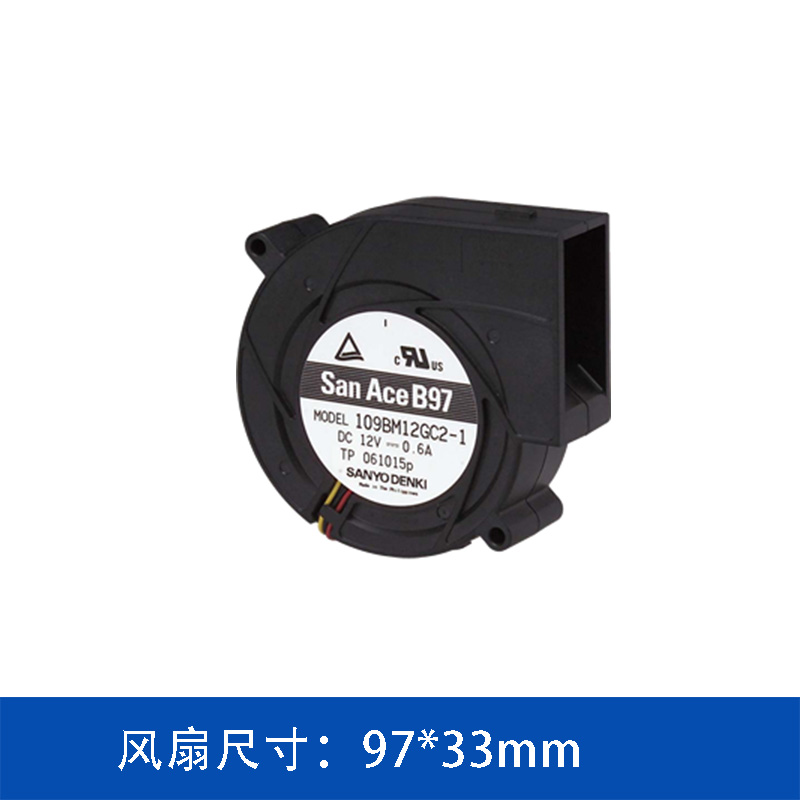
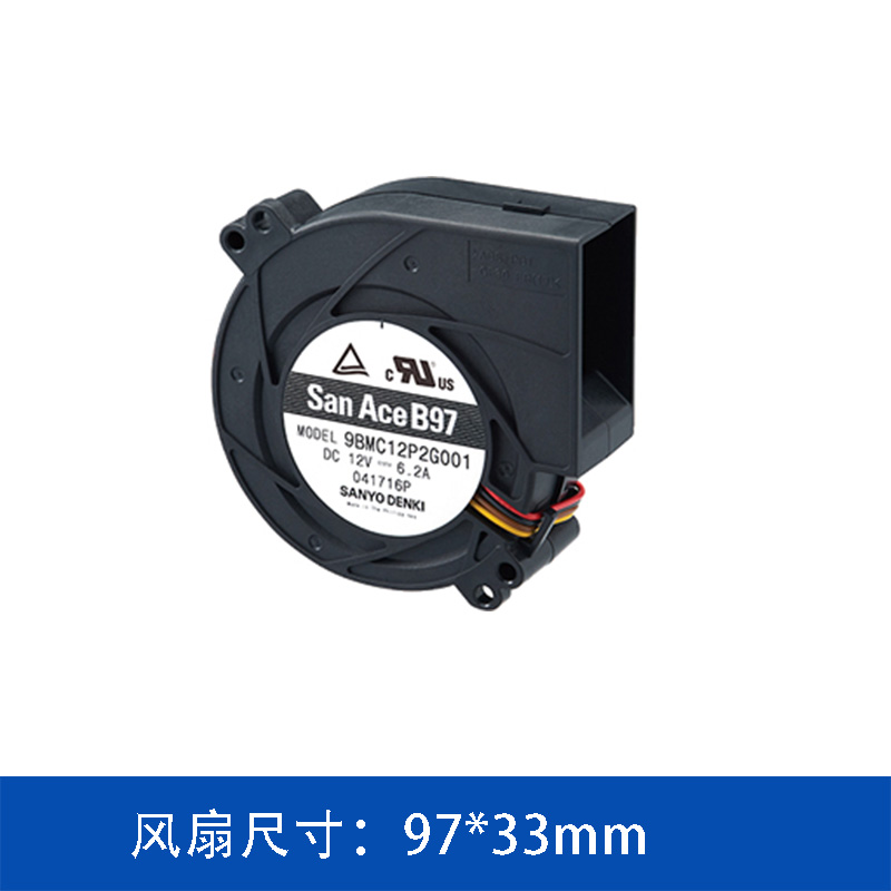
The 97×33mm San Ace blower family includes models with different performance levels.
When selecting a model, engineers should not simply choose the model with the highest rated airflow.
A more appropriate selection process is:
Step 1 — Determine the heat load
Estimate the heat generated by the electronic components that require cooling.
Step 2 — Establish the required temperature rise
Determine the maximum allowable component or internal air temperature.
Step 3 — Calculate the required airflow
Estimate the airflow required to remove the generated heat.
Step 4 — Evaluate system resistance
Consider heat sinks, filters, ducts, grilles and other airflow restrictions.
Step 5 — Check the fan performance curve
Find the operating point where the fan curve intersects the system resistance curve.
Step 6 — Confirm electrical and mechanical compatibility
Check voltage, current, dimensions, connector configuration, sensor requirements and installation orientation.
This approach is generally more reliable than selecting a blower according to CFM alone.
11. San Ace 9BMB12H201 at a Glance
The San Ace 9BMB12H201 provides a compact solution for applications requiring directional airflow and moderate-to-high static pressure within a 97×33mm installation format.
Its main specifications include:
-
97×97×33mm size
-
12V DC operation
-
13.2W rated power
-
4,850 min⁻¹ rated speed
-
39.2 CFM maximum airflow
-
490 Pa maximum static pressure
-
57 dBA noise level
-
Pulse Sensor
-
40,000 hours at 60°C / 70,000 hours at 40°C expected life
For compact electronic systems where airflow resistance is a significant design consideration, these characteristics make the 9BMB12H201 a model worth evaluating alongside the thermal and mechanical requirements of the complete system.
12. Conclusion
Cooling design for compact electronic equipment is not simply a matter of increasing airflow. As internal component density increases, the airflow path becomes increasingly important, and pressure loss across heat sinks, filters, ducts and ventilation structures can significantly affect the actual cooling performance.
The SANYO DENKI San Ace 9BMB12H201 combines a 97×33mm compact blower structure, 12V DC operation, 39.2 CFM maximum airflow and 490 Pa maximum static pressure, providing an option for equipment where installation space and airflow resistance need to be considered together.
For a final fan selection, engineers should evaluate the complete heat load, system impedance, fan performance curve, operating temperature, noise requirements and expected service life rather than relying on a single datasheet parameter.
 ∷
∷





 Click to inquire