San Ace 9BMB12F201: 12V 97×33mm DC Blower for Compact Electronic Cooling
Thermal management becomes increasingly difficult as electronic equipment becomes smaller and more densely populated. Components that once had sufficient natural airflow may require forced cooling when processors, power devices, communication modules and other heat sources are installed within a confined enclosure.
In these applications, the cooling fan must provide more than basic airflow. The ability to maintain airflow through internal resistance, while fitting into a limited installation space, can be equally important.
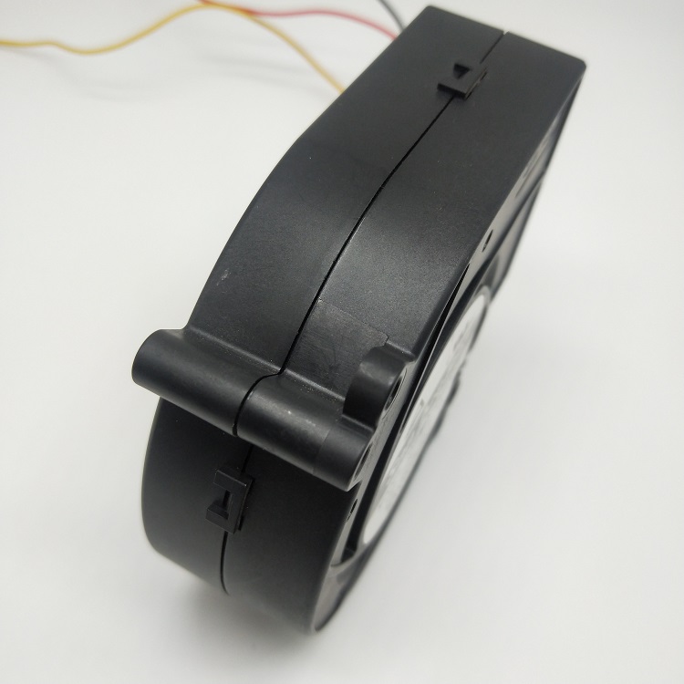
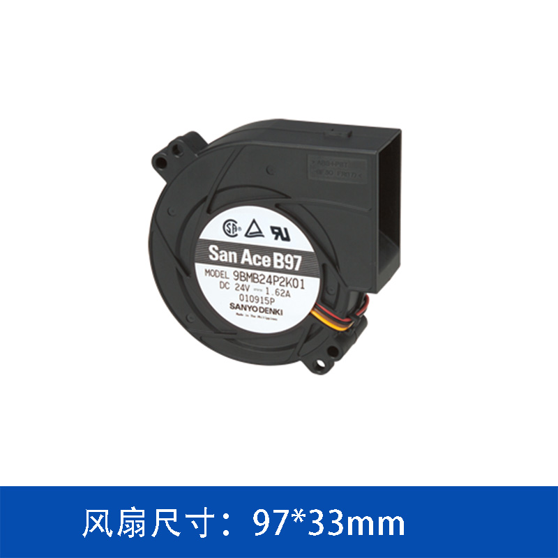
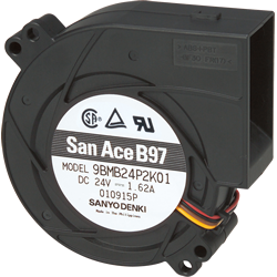
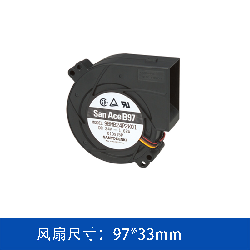
The SANYO DENKI San Ace 9BMB12F201 is a 97×97×33mm DC blower designed for compact cooling systems. Operating at 12 V DC, this model provides a maximum airflow of 36.7 CFM and a maximum static pressure of 410 Pa, with a rated speed of 4,500 min⁻¹.
1. San Ace 9BMB12F201 Specifications
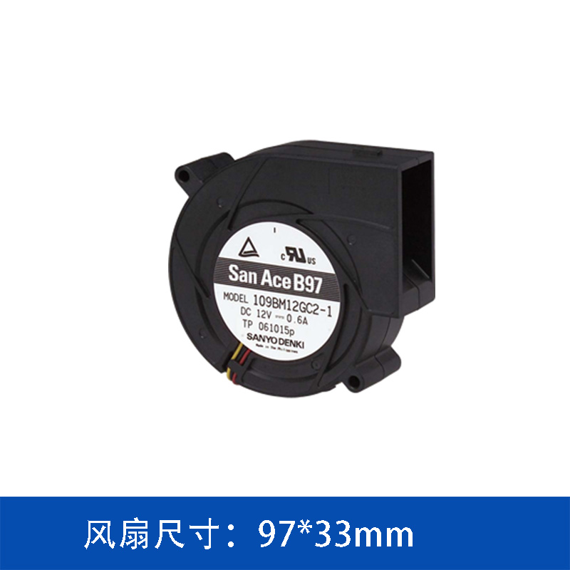
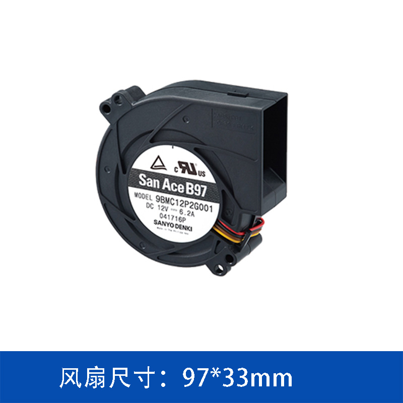
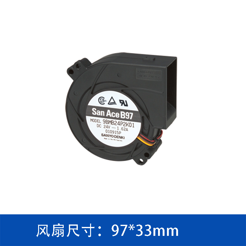
The 9BMB12F201 is part of the San Ace 97×33mm DC blower lineup. Its relatively compact dimensions make it suitable for equipment where the available cooling space is limited.
|
Parameter
|
Specification
|
|
Model
|
9BMB12F201
|
|
Product Type
|
DC Blower
|
|
Dimensions
|
97 × 97 × 33 mm
|
|
Rated Voltage
|
12 V DC
|
|
Rated Current
|
0.9 A
|
|
Rated Power
|
10.8 W
|
|
Rated Speed
|
4,500 min⁻¹
|
|
Maximum Airflow
|
1.04 m³/min
|
|
Maximum Airflow
|
36.7 CFM
|
|
Maximum Static Pressure
|
410 Pa
|
|
Maximum Static Pressure
|
1.647 inchH₂O
|
|
Noise Level
|
56 dBA
|
|
Sensor
|
Pulse Sensor
|
|
Expected Life
|
40,000 h at 60°C / 70,000 h at 40°C
|
|
PWM Control
|
No
|
The combination of 36.7 CFM airflow and 410 Pa static pressure makes the model suitable for cooling architectures where the airflow path has a certain level of resistance.
2. What Makes a Blower Suitable for Compact Equipment?
One of the main differences between a blower and a conventional axial fan is the way airflow is routed.
A blower can take in air through one direction and discharge it through an outlet positioned approximately 90 degrees from the intake direction.
This characteristic can provide greater flexibility when designing the internal airflow path.
For compact equipment, the cooling route may need to pass around:
-
Printed circuit boards
-
Heat sinks
-
Power modules
-
Cable assemblies
-
Structural panels
-
Filters
-
Internal partitions
Using a blower can help engineers establish a more suitable airflow direction without relying entirely on additional external ductwork.
3. 410 Pa Static Pressure and System Resistance
The maximum static pressure of the 9BMB12F201 is 410 Pa.
Static pressure is particularly relevant when air needs to pass through components that resist airflow.
Typical sources of pressure loss include:
-
Heat sinks
-
Dust filters
-
Narrow ventilation openings
-
Air ducts
-
Protective mesh
-
Dense electronic assemblies
-
Internal airflow channels
A fan's free-air airflow rating does not represent the airflow that will necessarily be achieved after installation.
Once the blower is installed into an actual device, the operating point depends on the interaction between the fan performance curve and the system resistance curve.
Therefore, a thermal design should evaluate both airflow and static pressure.
4. 36.7 CFM Maximum Airflow
The 9BMB12F201 provides a maximum airflow of:
1.04 m³/min
or approximately:
36.7 CFM
Airflow is one of the basic parameters used to estimate the amount of heat that forced air cooling can remove.
However, airflow should always be considered together with system resistance.
For example, a fan may demonstrate a relatively high airflow value in an unrestricted test condition, but the actual airflow may decrease considerably once the fan is installed behind a filter or connected to a narrow air passage.
This is why the fan's operating point is more useful than maximum airflow alone when evaluating an actual cooling system.
5. 97×33mm Compact Installation Format
The 97×97×33mm dimensions allow the 9BMB12F201 to be considered for equipment with limited internal installation space.
The 33mm thickness is particularly relevant for systems where the available depth is constrained.
Possible applications include:
-
Network equipment
-
Communication systems
-
Server equipment
-
Storage systems
-
Industrial controllers
-
Automation equipment
-
Power electronics
-
Electronic control systems
-
Compact computing equipment
Actual application suitability depends on the equipment's heat generation, airflow requirements and mechanical structure.
6. 12V DC Power Architecture
The 9BMB12F201 is rated for 12 V DC, with a rated current of 0.9 A and rated power of 10.8 W.
This makes the blower compatible with many low-voltage electronic systems.
When integrating the fan into equipment, engineers should verify:
-
Available DC supply voltage
-
Continuous current capacity
-
Startup characteristics
-
Connector configuration
-
Fan monitoring requirements
-
Control architecture
-
Electrical protection
The cooling fan should be evaluated as part of the complete equipment power system rather than as an isolated component.
7. Pulse Sensor for Fan Status Monitoring
The 9BMB12F201 includes a Pulse Sensor.
A pulse output can be used by the host system to monitor fan rotation.
For equipment where cooling reliability is important, fan monitoring can provide an additional layer of system protection.
Depending on the equipment design, the pulse signal can be used for:
Fan operation monitoring → abnormal-speed detection → alarm generation → maintenance response
This can be useful in systems that operate continuously or contain components with relatively high thermal sensitivity.
8. Noise Performance
The specified noise level of the 9BMB12F201 is 56 dBA.
The actual acoustic performance of a fan-installed system can differ from the datasheet value because the surrounding mechanical structure influences airflow noise and vibration.
For example, the following factors may affect system-level noise:
-
Enclosure geometry
-
Air inlet design
-
Outlet design
-
Heat sink structure
-
Duct configuration
-
Grilles
-
Resonance
-
Fan operating point
For applications where acoustic performance is important, testing the blower after installation is recommended.
9. Expected Service Life
The expected service life specified for the 9BMB12F201 is:
40,000 hours at 60°C
and
70,000 hours at 40°C.
The difference between these two conditions highlights the relationship between operating temperature and fan service life.
In practical equipment, the temperature around the fan may differ significantly from the surrounding room temperature.
Therefore, thermal engineers should consider the actual temperature surrounding the fan when estimating long-term reliability.
10. Applications for the 9BMB12F201
The performance characteristics of this model make it a potential option for a range of compact electronic cooling applications.
Communication Equipment
Communication systems often combine multiple heat-generating components within relatively small enclosures.
A blower can provide a controlled airflow path through the equipment.
Industrial Control Systems
Industrial controllers may contain processors, power supplies and other electronic components that generate heat during continuous operation.
Where internal airflow resistance is significant, static pressure becomes an important selection parameter.
Server and Storage Equipment
High-density computing and storage equipment can require forced airflow through heat sinks and restricted internal passages.
The blower configuration can help accommodate specific airflow-routing requirements.
Power Electronics
Power conversion and control devices can generate substantial heat, particularly during high-load operation.
A properly selected blower can be incorporated into the forced-air cooling architecture.
11. How Should Engineers Select a 97×33mm DC Blower?
Selecting a blower based solely on maximum airflow can produce an inaccurate thermal design.
A more complete evaluation should follow several steps.
Step 1: Determine the Heat Load
Identify the major heat-generating components and estimate the total heat that must be removed.
Step 2: Establish the Thermal Target
Define the maximum allowable temperature for critical components and the acceptable internal temperature rise.
Step 3: Estimate Required Airflow
Calculate the approximate airflow required to transport the generated heat away from the equipment.
Step 4: Map the Airflow Resistance
Identify pressure losses caused by filters, heat sinks, grilles, ducts and other restrictions.
Step 5: Determine the Operating Point
Use the fan performance curve and system resistance curve to determine the expected actual airflow.
Step 6: Check Mechanical and Electrical Integration
Finally, verify dimensions, voltage, current, sensor interface, mounting arrangement and available installation space.
This process provides a more realistic basis for fan selection than comparing CFM values alone.
12. Why 9BMB12F201 Can Be Considered for Lower-Power Cooling Designs
Within the San Ace 97×33mm blower family, the 9BMB12F201 represents a relatively moderate-performance configuration.
Its:
-
10.8 W rated power
-
4,500 min⁻¹ rated speed
-
36.7 CFM maximum airflow
-
410 Pa maximum static pressure
-
56 dBA noise level
provide a balance between cooling capability and electrical consumption.
This can make the model worth evaluating when an application does not require the higher airflow and pressure levels of more powerful 97×33mm blower models.
Instead of automatically selecting the highest-performance fan, engineers can compare the required system operating point with the available blower models and select a configuration that provides sufficient thermal margin without unnecessary capacity.
13. San Ace 9BMB12F201 Summary
The SANYO DENKI San Ace 9BMB12F201 is a compact 12V DC blower measuring 97×97×33mm.
Its key characteristics include:
-
12 V DC rated voltage
-
0.9 A rated current
-
10.8 W rated power
-
4,500 min⁻¹ rated speed
-
36.7 CFM maximum airflow
-
410 Pa maximum static pressure
-
56 dBA noise level
-
Pulse Sensor
-
40,000 hours at 60°C expected life
-
70,000 hours at 40°C expected life
The model is intended to be evaluated as part of a complete thermal management system, particularly where equipment size, airflow direction and system impedance all influence the cooling design.
14. Conclusion
As electronic equipment becomes more compact, the thermal design challenge increasingly shifts from simply generating airflow to delivering usable airflow through the actual system.
Heat sinks, filters, narrow air passages and dense component layouts can all increase system impedance. In these situations, static pressure and airflow must be considered together.
The San Ace 9BMB12F201 combines a compact 97×33mm blower format with 36.7 CFM maximum airflow and 410 Pa maximum static pressure, while operating from a 12V DC supply. Its Pulse Sensor also provides an option for monitoring fan rotation within the host equipment.
For engineers evaluating this model, the most important step is to match the blower's performance curve with the actual system resistance and thermal load. This provides a more reliable basis for determining whether the 9BMB12F201 is suitable for the intended cooling application.
 ∷
∷




 Click to inquire