SANYO DENKI San Ace 9BMB12S201 12V DC Blower Fan for Compact Electronic Equipment
As electronic equipment becomes smaller while its processing and power density continue to increase, thermal management is becoming increasingly dependent on the design of the internal airflow path.
In many compact devices, the available installation space is limited and the cooling air cannot simply move directly through the enclosure. Heat sinks, filters, narrow ventilation passages and densely packed components can all increase airflow resistance.
For these applications, a blower can provide an alternative to a conventional axial fan by combining compact installation with directional airflow and static pressure capability.
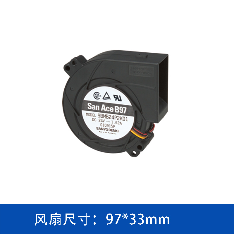
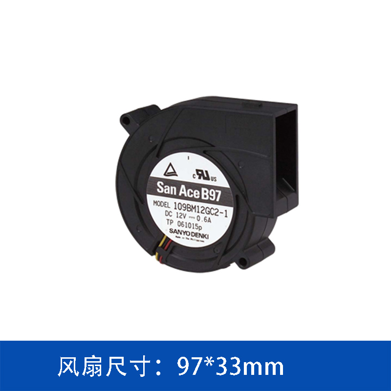
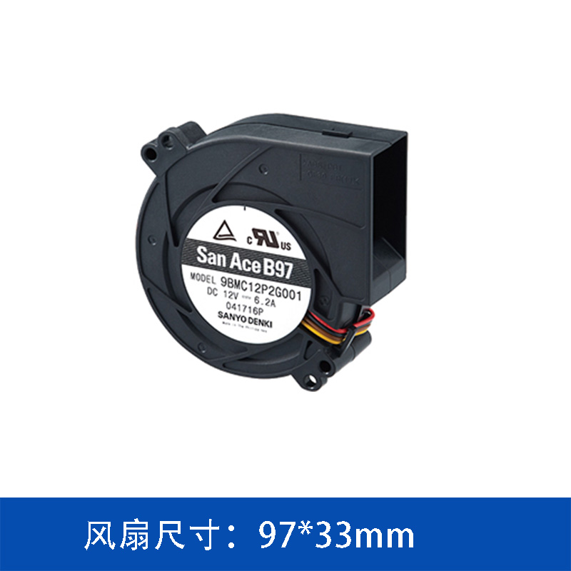
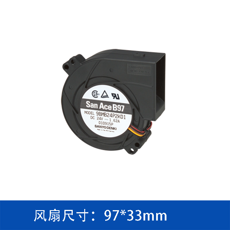
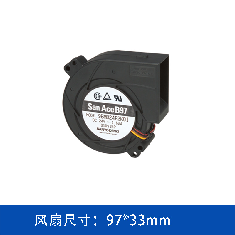
The SANYO DENKI San Ace 9BMB12S201 is a 97 × 33 mm DC blower rated for 12 V operation. It provides a maximum airflow of 43.1 CFM and a maximum static pressure of 610 Pa, making it suitable for a range of compact electronic cooling applications.
1. 97 × 33 mm Compact DC Blower Design
The 9BMB12S201 adopts a 97 mm-class blower design with a 33 mm thickness.
The compact dimensions are useful for equipment where the cooling component must fit into a restricted internal space.
Unlike an axial fan, which generally discharges air in the same general direction as its intake axis, a blower uses its housing and impeller structure to redirect the airflow.
This allows the blower to discharge air approximately 90 degrees from the intake direction.
For equipment designers, this characteristic can simplify the internal airflow layout and reduce the need for additional external ducting.
2. Main Specifications of the 9BMB12S201
The primary specifications of the San Ace 9BMB12S201 are shown below.
|
Parameter
|
Specification
|
|
Model
|
9BMB12S201
|
|
Product type
|
DC Blower
|
|
Size
|
97 × 33 mm
|
|
Rated voltage
|
12 V DC
|
|
Rated current
|
1.4 A
|
|
Rated power
|
16.8 W
|
|
Rated speed
|
5,250 min⁻¹
|
|
Maximum airflow
|
1.22 m³/min
|
|
Maximum airflow
|
43.1 CFM
|
|
Maximum static pressure
|
610 Pa
|
|
Maximum static pressure
|
2.45 inchH₂O
|
|
Noise
|
59 dBA
|
|
Sensor
|
Pulse sensor
|
|
Expected life
|
40,000 h at 60°C / 70,000 h at 40°C
|
|
PWM control
|
No
|
These specifications place the 9BMB12S201 in a range suitable for compact systems where a combination of moderate airflow, static pressure and controlled airflow direction is required.
3. 43.1 CFM Airflow in a Compact Form Factor
The 9BMB12S201 provides a maximum airflow of 1.22 m³/min, equivalent to 43.1 CFM.
However, the maximum airflow value represents a free-air condition and should not be interpreted as the actual airflow inside an assembled device.
Once the blower is installed into equipment, the airflow will be affected by system resistance.
Typical sources of pressure loss include:
-
Heat sink structures
-
Dust filters
-
Protective grilles
-
Narrow ventilation openings
-
Internal ducts
-
PCB components
-
Cable harnesses
-
Enclosure structures
Consequently, the actual airflow must be determined from the intersection between the fan performance curve and the system resistance curve.
This is particularly important when comparing a blower with conventional axial cooling fans.
4. 610 Pa Static Pressure for Restricted Cooling Paths
The 9BMB12S201 has a maximum static pressure of 610 Pa.
Static pressure describes the fan's ability to generate pressure against resistance in the airflow system.
When an electronic device has a relatively open ventilation path, airflow capacity may be the dominant selection parameter.
However, when airflow must pass through a restrictive path, pressure capability becomes increasingly important.
For example, consider an equipment enclosure containing a dense heat sink.
The cooling air must pass through the heat sink fins before leaving the equipment. The narrower the airflow passage and the greater the restriction, the more pressure the cooling fan needs to maintain useful airflow.
Therefore, engineers should evaluate the airflow-pressure relationship rather than selecting a fan according to maximum CFM alone.
5. Why Use a Blower Instead of an Axial Fan?
The choice between an axial fan and a blower depends largely on the equipment's airflow architecture.
An axial fan is often suitable when:
Air inlet → Fan → Heat-generating components → Exhaust
can be arranged in a relatively straight path.
A blower can be more convenient when the system requires:
Air inlet → Blower → 90° airflow direction → Cooling channel → Heat source
This difference can be valuable in compact equipment.
The blower can be positioned according to the available mechanical space while directing the discharge airflow toward a heat sink, electronic module or designated ventilation channel.
As a result, blower technology is often considered for equipment where mechanical packaging and airflow routing are closely interconnected.
6. 16.8 W Rated Power and 5,250 min⁻¹ Speed
The 9BMB12S201 is rated at 16.8 W and operates at a rated speed of 5,250 min⁻¹.
The combination provides the rotational energy required to generate airflow and static pressure within a compact blower structure.
For equipment manufacturers, fan power consumption should also be considered as part of the overall thermal design.
The cooling system needs to remove heat generated by the primary electronics, but the fan itself also consumes electrical power.
Therefore, fan selection should consider:
-
Required cooling capacity
-
Fan power consumption
-
Airflow resistance
-
Operating temperature
-
Noise requirements
-
Expected service life
The goal is not simply to select the highest-speed fan, but to identify a fan that provides sufficient cooling at the required system operating point.
7. Pulse Sensor for Fan Monitoring
The 9BMB12S201 incorporates a pulse sensor.
In applications where cooling fan operation needs to be monitored, a pulse signal can provide the control system with information about fan rotation.
This can support system-level functions such as:
-
Fan rotation monitoring
-
Fan failure detection
-
Abnormal operating condition detection
-
Thermal protection
-
Maintenance alerts
For servers, communication equipment and other continuously operating electronic systems, monitoring the cooling fan can be an important part of overall equipment reliability.
8. Expected Life at Different Operating Temperatures
The specified expected service life of the 9BMB12S201 is:
40,000 hours at 60°C
and
70,000 hours at 40°C.
This difference illustrates why operating temperature is an important consideration in cooling fan selection.
The actual service life of a fan depends on the application environment and operating conditions. Fan temperature, ambient temperature, operating speed and equipment airflow design can all affect long-term performance.
For this reason, engineers should consider the actual thermal environment around the fan rather than evaluating service life independently from system temperature.
9. Potential Applications
The compact configuration and static pressure characteristics of the 9BMB12S201 make it suitable for consideration in a variety of electronic equipment.
Server and Storage Equipment
Servers and storage systems often contain high-density electronic components and restricted internal airflow paths.
A blower can be useful when cooling air needs to be redirected through heat sinks or dedicated internal channels.
Communication Equipment
Communication equipment and base-station-related electronics may require continuous forced-air cooling.
The 12 V DC configuration can be integrated into electronic systems with an appropriate low-voltage DC power architecture.
Industrial Controllers
Industrial control equipment can contain processors, power supplies and communication modules inside compact enclosures.
Where natural convection is insufficient, a compact blower can provide forced airflow through designated cooling paths.
Power Electronics
Power conversion and control equipment can generate considerable heat within a relatively small installation volume.
A blower can help direct cooling air toward heat-generating components where the enclosure layout does not permit a simple straight-through airflow path.
10. Key Selection Considerations
Before selecting the 9BMB12S201 for a specific application, engineers should evaluate the complete cooling system rather than relying on a single fan specification.
Airflow requirement
Determine the heat load and calculate the airflow required to maintain the target component temperature.
System pressure loss
Evaluate the pressure drop caused by heat sinks, filters, grilles, ducts and other airflow restrictions.
Operating point
Use the fan performance curve together with the system impedance curve to determine the actual airflow.
Mechanical compatibility
Confirm the available installation space and airflow inlet/outlet orientation.
Electrical compatibility
The 9BMB12S201 is rated for 12 V DC, 1.4 A and 16.8 W.
Monitoring requirements
If the equipment requires fan monitoring, verify compatibility with the model's pulse sensor.
Conclusion
The SANYO DENKI San Ace 9BMB12S201 is a compact 97 × 33 mm 12 V DC blower fan designed for electronic equipment where airflow direction, installation space and system resistance need to be considered together.
With a maximum airflow of 43.1 CFM and maximum static pressure of 610 Pa, the model can be considered for cooling systems with restricted airflow paths, including servers, storage equipment, communication equipment, industrial controllers and power electronics.
Its 16.8 W rated power, 5,250 min⁻¹ speed, pulse sensor and specified service life of up to 70,000 hours at 40°C provide additional parameters for engineers evaluating the model for long-term cooling applications.
For the final selection, however, the most important step is to match the blower's performance curve with the actual system impedance. The correct cooling fan is determined by its operating point within the equipment, not simply by its maximum airflow rating.
 ∷
∷




 Click to inquire