SANYO DENKI San Ace 9BMB12P2G01: 12V 97×33 mm Blower Cooling Fan for Compact Electronic Equipment
As electronic equipment continues to become more compact, thermal management is becoming increasingly dependent on the design of the internal airflow path.
Servers, storage systems, communication equipment, industrial controllers, and other electronic devices often have limited installation space while containing multiple heat-generating components. Heat sinks, filters, grilles, narrow airflow channels, and dense component layouts can also create considerable airflow resistance.
In these applications, a conventional axial cooling fan may not always provide the required airflow direction or static pressure.
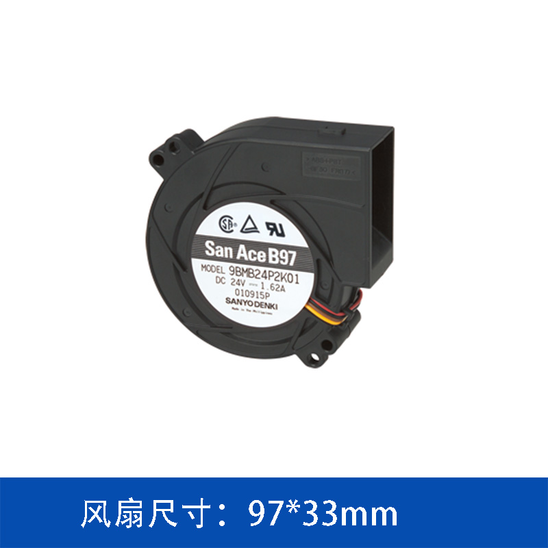
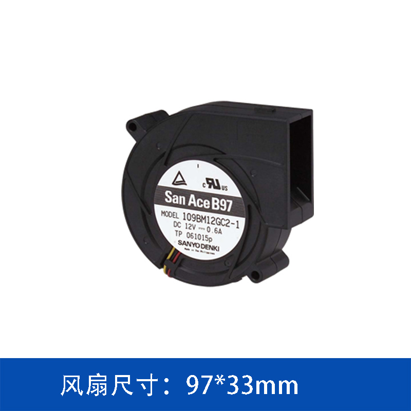
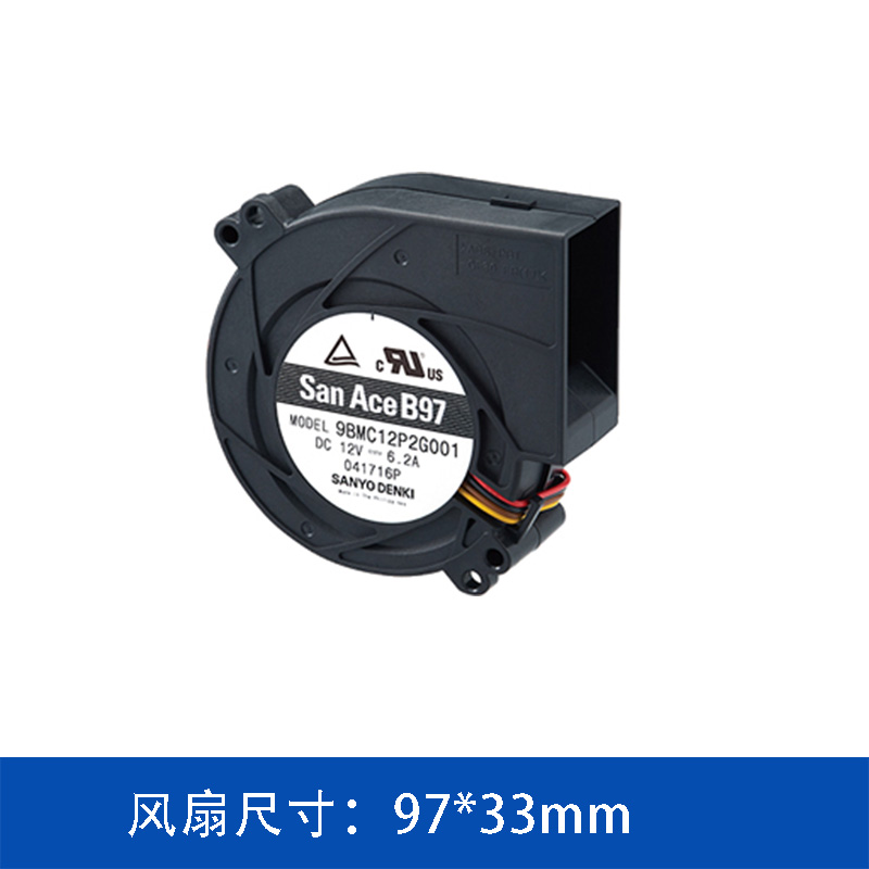
The SANYO DENKI San Ace 9BMB12P2G01 is a 12V DC blower cooling fan with a compact 97×33 mm form factor, providing a balance of airflow, static pressure, compact installation, and controllable operation.
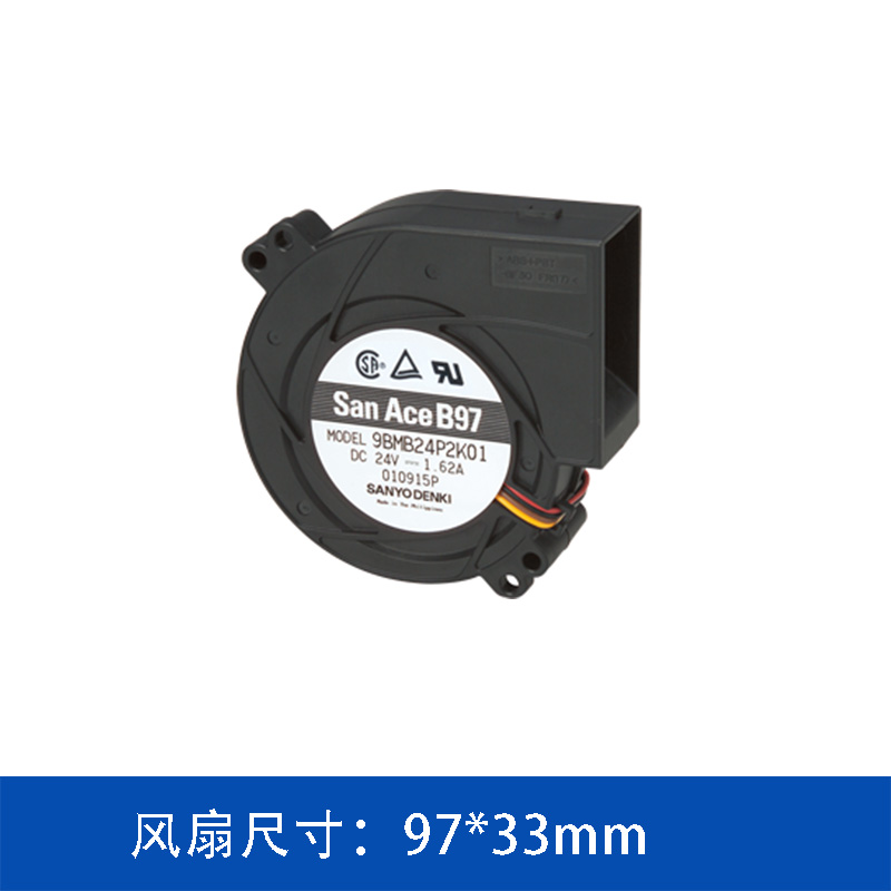
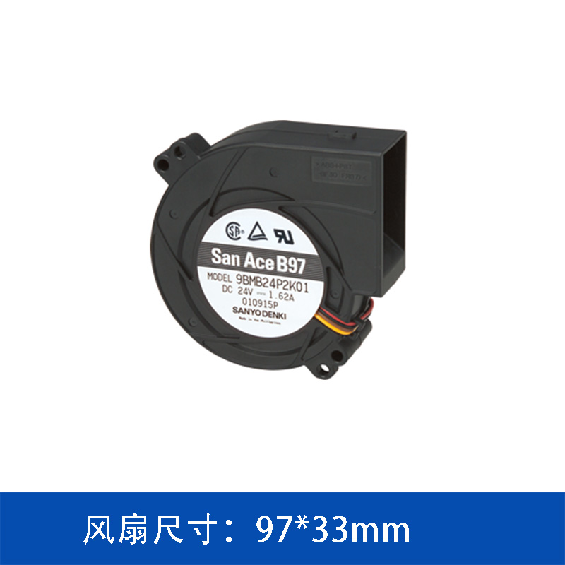
97×33 mm Compact Blower Design
The San Ace 9BMB12P2G01 measures 97 mm in diameter with a 33 mm thickness, making it part of the compact 9733 blower category.
The blower configuration differs from a conventional axial fan in its airflow direction.
A blower draws air through the intake and discharges it at approximately 90 degrees from the intake direction. This can simplify airflow routing inside compact equipment because the airflow direction can be changed without necessarily adding an external duct.
For equipment designers, this can provide greater flexibility when arranging:
-
Heat sinks
-
Power components
-
Circuit boards
-
Storage devices
-
Internal air channels
-
Ventilation openings
The compact form factor is particularly useful where the available installation space is limited.
760 Pa Static Pressure for Airflow-Resistant Systems
One of the important specifications of the 9BMB12P2G01 is its maximum static pressure of 760 Pa.
Static pressure is an important parameter when selecting a cooling fan for equipment with airflow resistance.
In a real electronic system, the cooling air rarely moves through an unrestricted path. Instead, it may have to pass through heat sinks, filters, grilles, narrow channels, or densely arranged components.
Each restriction increases system impedance.
Therefore, a fan's maximum airflow under free-air conditions does not necessarily represent the airflow that will be achieved after installation.
The actual cooling performance depends on the interaction between the fan and the equipment:
Fan performance curve + system resistance curve = actual operating point
For this reason, the 760 Pa maximum static pressure of the 9BMB12P2G01 should be considered together with the airflow requirement and system impedance when selecting the fan.
Up to 47.3 CFM Airflow
The San Ace 9BMB12P2G01 provides a maximum airflow of:
This airflow capacity provides forced-air cooling for compact electronic systems with moderate to significant heat generation.
However, maximum airflow is normally measured under free-air conditions.
Once the blower is installed inside an actual device, airflow will be affected by the resistance of the complete ventilation system.
For engineering applications, it is therefore more useful to consider the required airflow at the actual system operating point rather than simply comparing maximum CFM values.
A typical selection process can be expressed as:
Heat generation → required heat dissipation → required airflow → system impedance → fan operating point
This approach helps engineers evaluate whether the selected blower can provide sufficient cooling under actual operating conditions.
12V DC Operation with 21.6 W Rated Power
The 9BMB12P2G01 is designed for a 12V DC power supply.
Its main specifications are:
|
Parameter
|
Specification
|
|
Model
|
9BMB12P2G01
|
|
Product Type
|
Blower
|
|
Size
|
97 × 33 mm
|
|
Rated Voltage
|
12 V DC
|
|
Rated Current
|
1.8 A
|
|
Rated Power
|
21.6 W
|
|
Rated Speed
|
5,750 min⁻¹
|
|
Maximum Airflow
|
1.34 m³/min / 47.3 CFM
|
|
Maximum Static Pressure
|
760 Pa / 3.05 inchH₂O
|
|
Noise Level
|
61 dBA
|
|
Sensor
|
Pulse sensor
|
|
PWM Control
|
Yes
|
|
Expected Life
|
40,000 h at 60°C / 70,000 h at 40°C
|
The 12V DC configuration makes this model suitable for equipment platforms that use a 12V power architecture.
With a rated power of 21.6 W, it provides a lower-power alternative within the 97×33 mm San Ace blower lineup while still offering substantial airflow and static pressure.
PWM Control for Adjustable Cooling Performance
The 9BMB12P2G01 supports PWM control.
This allows the cooling system to adjust the blower's operating speed according to the thermal condition of the equipment.
Electronic equipment does not always operate at the same thermal load.
For example, a communication device may operate at a relatively low load during standby or normal operation but generate significantly more heat during peak processing.
Similarly, industrial equipment may experience different thermal conditions depending on the operating cycle.
With PWM control, the cooling strategy can be adjusted accordingly:
Low thermal load → lower fan speed
High thermal load → higher fan speed
This provides equipment designers with greater flexibility when balancing thermal performance, noise, and fan power consumption.
The actual control logic should be determined according to the thermal characteristics and control architecture of the target equipment.
Pulse Sensor for Fan Monitoring
The San Ace 9BMB12P2G01 is equipped with a pulse sensor.
The pulse signal can be used by the equipment controller to monitor fan operation and rotational status.
For systems where cooling performance is directly related to equipment reliability, this type of monitoring can be useful.
If the fan stops or its rotational speed changes unexpectedly, the equipment controller can use the pulse signal as part of its fault detection or protection strategy.
This is particularly relevant to equipment designed for continuous operation, where an unnoticed cooling fan failure could lead to excessive internal temperatures.
Expected Service Life: Up to 70,000 Hours at 40°C
The specified expected service life of the 9BMB12P2G01 is:
40,000 hours at 60°C
or
70,000 hours at 40°C
Operating temperature is an important consideration when evaluating cooling fan service life.
The temperature around the fan inside an electronic enclosure can differ considerably from the ambient temperature because of heat generated by processors, power supplies, batteries, drives, and other components.
Therefore, engineers should consider the actual temperature around the cooling fan when evaluating long-term reliability.
Fan position, airflow direction, enclosure structure, heat generation, and ambient conditions can all affect the operating environment.
Applications of the 9BMB12P2G01
The compact size and blower configuration make the 9BMB12P2G01 suitable for a variety of electronic cooling applications.
Server Cooling
Servers contain multiple heat-generating components in a relatively compact enclosure.
Processors, memory, storage devices, power supplies, and heat sinks can create complex airflow paths with considerable system resistance.
The 9BMB12P2G01 combines 47.3 CFM maximum airflow with 760 Pa maximum static pressure, making it suitable for cooling systems where both airflow capacity and pressure performance need to be considered.
Storage Systems
Storage systems often require continuous cooling for drives, controllers, processors, and power components.
The compact 97×33 mm blower format can be useful when installation space is limited.
The 90-degree airflow discharge characteristic also provides greater flexibility when designing internal airflow paths.
Communication Equipment
Communication and networking equipment can operate continuously and may experience varying thermal loads.
The combination of:
-
12V DC operation
-
PWM control
-
Pulse sensor
-
Compact blower construction
-
760 Pa maximum static pressure
allows the model to be considered for a range of communication and electronic equipment cooling applications.
Industrial Electronic Equipment
Industrial controllers, test equipment, power electronics, automation equipment, and other electronic systems can contain densely arranged components and restricted airflow channels.
In these applications, blower fans can provide an alternative to conventional axial fans when airflow direction and system impedance are important design considerations.
Why Static Pressure Should Be Considered Along with Airflow
When selecting a cooling fan, maximum airflow is often one of the first specifications engineers compare.
However, higher CFM does not automatically mean better cooling performance.
Consider an electronic enclosure with a dense heat sink and narrow ventilation channel.
The fan may provide 47.3 CFM under free-air conditions, but the actual airflow after installation will be lower because of system resistance.
This is why static pressure matters.
A cooling fan with an appropriate pressure capability can maintain useful airflow against system resistance.
For the 9BMB12P2G01, the maximum static pressure is 760 Pa, while maximum airflow reaches 47.3 CFM.
The final fan selection should therefore be based on the actual intersection between the fan performance curve and the equipment's system resistance curve.
9BMB12P2G01 at a Glance
The SANYO DENKI San Ace 9BMB12P2G01 provides a compact cooling solution for electronic equipment requiring controlled forced-air cooling.
Its key characteristics include:
-
97×33 mm compact blower design
-
12V DC rated voltage
-
21.6 W rated power
-
5,750 min⁻¹ rated speed
-
47.3 CFM maximum airflow
-
760 Pa maximum static pressure
-
61 dBA noise level
-
PWM control
-
Pulse sensor
-
40,000-hour expected life at 60°C
-
70,000-hour expected life at 40°C
The combination of these characteristics makes the model suitable for applications where installation space, airflow direction, system impedance, and controllable cooling performance all need to be considered.
Conclusion
The SANYO DENKI San Ace 9BMB12P2G01 is a 12V, 97×33 mm blower cooling fan designed for compact electronic equipment.
With a maximum airflow of 47.3 CFM and maximum static pressure of 760 Pa, the model provides a practical balance between airflow capacity and pressure performance. Its PWM control allows the cooling output to be adjusted according to equipment thermal demand, while the pulse sensor provides a means of monitoring fan operation.
For servers, storage systems, communication equipment, industrial electronics, and other compact devices, the 9BMB12P2G01 can be evaluated as a cooling solution where airflow resistance and installation space are important design factors.
When selecting the appropriate cooling fan, engineers should evaluate the complete thermal system—including heat generation, required airflow, system impedance, fan operating point, operating temperature, noise requirements, control method, and expected service life—rather than selecting a model based on maximum airflow alone.
 ∷
∷




 Click to inquire